Showing posts with label Power Amplifier. Show all posts

LM1875 80W audio power amplifier circuit and explanation

LM1875 80W audio power amplifier circuit and explanation

A very simple high efficiency 80W audio power amplifier project can be designed using the LM3875 power audio IC . LM3875 is a high-performance audio power amplifier capable of delivering 56W of continuous average power to an 8Ω load with 0.1% THD+N from 20Hz to 20kHz .
By connecting two LM39875 audio IC in bridge mode this audio power amplifier will deliver 80 watt of output power into an 8 Ohm load. The LM3875 IC devices should be suitably heatsinked.
As you can see in the circuit diagram , this power audio amplifier require few external electronic parts .

The LM3875 maintains an excellent signal-to-noise ratio of greater than 95dB(min) with a typical low noise floor of 2.0μV.
This 80W audio power amplifier module accepts a wide range input voltage from 20 up to 84 volts, but typically is recommended ( for this circuit ) a dual +/-25 volts DC power supply .
Some features of this 80W audio power amplifier project based on the LM1875 IC are :
output protection from a short to ground or to the supplies via internal current limiting circuitry ,output over-voltage protection against transients from inductive loads ,supply under-voltage protection .

STK404-130S bassed 100w power amplifier circuit and explanation

STK404-130S bassed 100w power amplifier circuit and explanation

A very high power and efficiency 100w power amplifier electronic project can be designed using the STK404 audio power amplifier hybrid ICs that consist of optimally-designed discrete component power amplifier circuits that have been miniaturized using SANYO’s unique insulated metal substrate technology (IMST).

STK404 power audio IC is pin to pin compatible with some other STK series power amplifiers ranging from 45W to 180W (10%/1kHz) .
This audio power amplifier use the STK404-130S audio IC that will provide a maximum of 100 watt output power on a 6 ohms load with 0.4% THD . Using the same IC , can be obtained an output power of 150 watts with 10% THD.
The STK404-130S power audio IC supports a maximum input DC voltage of 64 volts , but typically is recommended a 45 volt dual ( +/-) power supply.
Like other audio amplifiers electronic projects , this high power 100w power amplifier circuit require a very well filtered DC power supply .
Because of the power dissipation , the STK404-130S hybrid audio power IC must be mounted on a heatsink . Therefore, the thermal resistance that satisfies all requirements of these power audio amplifier (for a guaranteed ambient temperature of 50°C) is 1.48°C/W.


TDA2030 bridge 35 watt power amplifier circuit and explanation

TDA2030 bridge 35 watt power amplifier circuit and explanation

A very simple 35 watt power amplifier electronic project can be designed using the TDA2030 power audio IC. The TDA2030A is a monolithic IC in Pentawatt package intended for use as low frequency class AB amplifier.
The TDA2030A provides high output current and has very low harmonic and cross-over distortion. TDA2030 ICs connected in bridge mode.
This circuit require few external electronics parts and supports a 8 ohms load . This 35 watt power amplifier require a very good filtered DC power supply , that will provide an output voltage of +/- 16 volts .

Using this circuit you can design a very simple and efficiency subwoofer amplifier with a maximum output power of 35 watt power .
The device incorporates a short circuit protection system comprising an arrangement for automatically limiting the dissipated power so as to keep the working point of the output transistors within their safe operating area. Also a conventional thermal shut-down system is also included .
However a heatsink must be used for the TDA2030 bridge circuit but for any reason, if the junction temperature increases up to 150oC, the thermal shut-down simply reduces the power dissipation and the current consumption.


STK433-730-E 60 watt stereo power audio amplifier circuit and explantion

A very simple high efficiency 60 watt stereo power audio amplifier circuit can be designed using the STK433-730-E hybrid IC designed to be used in class AB audio power amplifiers.

STK433-730-E 60 watt stereo power audio amplifier circuit and explantion
This class AB audio stereo power amplifier circuit will provide an output power of 30 watt on two channels at a 6 ohms load . Also this AB audio power amplifier circuit supports a 4 ohms load . For maximum rating on a 6 ohms load this stereo power amplifier project must be powered from a dual 28 volt very good filtered DC power source . For maximum rating on a 4 ohms load this 60 watt stereo power amplifier must be powered from a dual 25 volt DC power source , but typically is recommended a dual 18 volts DC power source on a 4 ohms load .
If is used to provide maximum ratings the output power will have a maximum 10% THD .
Exceeding the maximum ratings, even momentarily, may cause damage to the hybrid IC.
Use the hybrid IC so that the voltage applied to the stand-by pin (pin 13) never exceeds the maximum rating. The power amplifier is turned on by applying +2.5V to +5.5V to the stand-by pin (pin 13).

An output limiting circuit for substrate overheating is incorporated to protect the hybrid IC from the heat generation exceeding the maximum rating.
The load short-circuit protection circuit is activated when it has detected an overcurrent in the output transistors.
However a thermoplastic adhesive resin is used to secure the case and aluminum substrate.
When the IC supply voltage, VCC, is .18V and RL is 4 , the total power dissipation, Pd, within the hybrid IC, will be a maximum of 33Wat 1kHz for a continuous sine wave signal according to the Pd-PO characteristics.
STK433-730-E 60 watt stereo power audio amplifier circuit and explantion
Therefore, the value of 3.10.C/W, is the required thermal resistance of the heat sink.

LM2876 40W audio power amplifier circuit and explanation

LM2876 40W audio power amplifier circuit and explanation
Using the LM2876 high-performance audio power amplifier circuit can be designed a very simple high efficiency power audio amplifier electronic project capable of delivering 40W of continuous average power to an 8Ω load with 0.1% THD+N from 20Hz–20kHz.
The performance of the LM2876 high-performance audio power amplifier, utilizing its Self Peak Instantaneous Temperature (°Ke) (SPiKe™) protection circuitry, puts it in a class above discrete and hybrid amplifiers by providing an inherently, dynamically protected Safe Operating Area (SOA). SPiKe protection means that these parts are completely safeguarded at the output against overvoltage, undervoltage, overloads, including shorts to the supplies, thermal runaway, and instantaneous temperature peaks.
The LM2876 maintains an excellent signal-to-noise ratio of greater than 95dB (min) with a typical low noise floor of 2.0μV.

As you can see in the circuit diagram , this 40W high-performance audio power amplifier electronic project require few external electronic parts and require few knowledge .
The muting function of the LM2876 allows the user to mute the music going into the amplifier by drawing less than 0.5 mA out of pin 8 of the device.
Upon system power-up the under-voltage protection circuitry allows the power supplies and their corresponding caps to come up close to their full values before turning on the LM2876 such that no DC output spikes occur.
The LM2876 contains overvoltage protection circuitry that limits the output current to approximately 4Apeak while also providing voltage clamping, though not through internal clamping diodes.
The LM2876 has a sophisticated thermal protection scheme to prevent long-term thermal stress to the device. When the temperature on the die reaches 165°C, the LM2876 shuts down. It starts operating again when the die temperature drops to about 155°C
The LM2876 high-performance audio power amplifier circuit operates over a wide input voltage range , from 20 up to 70 volts , but typically a dual 30 volt power supply ( or a single 60 volt in this case ) will be work fine

TC9153AP electronic control volume TC9153AP electronic control volumeI have recently designed a small amplifier, use, self-satisfied, see below. The


TC9153AP electronic control volumeI have recently designed a small amplifier, use, self-satisfied, see below. The IC low power consumption, small distortion, the volume attenuation range of 0 ~ 66 dB, for every 2 dB step (that is, every click the Change button 2 dB), through AN1, AN2 control the volume to overcome the potential for moving in the rotation when the noise generated and Defects such as short life. Thick output by Toshiba original block TA8216H, the IC to 30 W × 2, voices thorough, bright, especially bass flexibility satisfactory, the whole range performed well. TA8216H to be fitted with heat sink and can not be connected to. I used STK6153 removed on the heat sink, it is appropriate.

2.5 W FM Power Amplifier This rf power amplifier design for a 2.5 Watt power amplifier for the FM band. An input of 50 mW gives a final output power

2.5 W FM Power Amplifier

This rf power amplifier design for a 2.5 Watt power amplifier for the FM band. An input of 50 mW gives a final output power of 2.5 Watts with a 13 Volt supply. The best bit is that the amplifier requires no tuning once it's built - it gives roughly the same gain and output power right across the FM band from 88 to 108 MHz.


There's even some hefty output low pass filtering to make sure that harmonic output is small and no interference is caused to users (mostly military!) on multiples of the FM frequency being amplified. A nice design based on, believe it or not, a military one...!
Source
: ZFM
Bookmark and Share

TDA2030 Power Amplifer circuit diagram

This is an audio power amplifier circuit using only a single chip and few passive components, that you can build 8-14 Watt audio power amplifier using TDA2030 chip. This is the figure of the circuit.


When you use 4 ohm speaker then you get 14 Watt output power, and around 8 Watt if you use 8 ohm loudspeaker. Make sure the 100n and 100u capacitor is wired as close as possible to the power input pin of the TDA 2030. You might wonder why we use 100uF and 100nf in parallel, if you think that we need 100.1uF capacitor then you’re wrong. All we need is just a capacitor around 100uF with small equivalent series inductance. At low frequency, the “relatively high” series inductance of the 100uF electrolytic capacitor can be neglected, but not for the high frequency. At high frequency, the TDA2030 is protected from instability by the 100nF capacitor, because the signals find the low inductance path here to bypass the fast power source variation.

600 WATT HI-FI Power Amplifier PA600


Attached is the schematic of a PA or subwoofer power amplifier capable of delivering about 650W RMS into 4 loads. The original design was called ’PA 600’ and was first published in the German magazine ’Elrad’ in 1990.
Towards the end of 1995, a scaled-down version of this circuit appeared in ’Elektor’ as ’PA 300’.
It is virtually the same circuit except for a less powerful output stage (now two complementary
pairs instead of five with additional driver stage) and minor changes in component selection and values. However, as ’Elektor’ is much more popular, many people built a ’PA 300’ without knowing it was scaled down from a bigger amplifier.
MORE.... click Here
OTHER.... click Here


http://kitaudio.blogspot.com AUDIO KIT =====>> Thanks For Coming...!! =====>> =====>>
audio kit
Under Creative Commons License: Attribution

Class A Power Amplifier by IRF530N+78L05

Class A Power Amplifier by IRF530N+78L05

This is the best design I have came up so far!
I use two 6x6x4cm heatsinks per channel. Power supply is unregulated (just transformer, diode bridge and capacitors) but I cannot hear anything even when I put my ear within few centimeters of the loudspeaker. Opamp has very good power supply rejection ratio. I’ve tried to keep everything as simple as possible and basically LM317 would be just one extra opamp… If you are looking for better sound, get separate regulated low power supply just for the U1 opamp, something like +-15V at 100-200 mA.
I have also used one LM7805 to get bias for both channels – you may want to use two separate 7805 in a final amp to get better channel separation. R2 pot is anything from 500 to 50k. I have used 22k.

Read More Source:

http://www.geocities.com/leobodnar/audio_amplifiers.html

Thank you.

Simple Class A Power Amplifier by IRF530

Simple Class A Power Amplifier by IRF530

I was in need of high quality headphones amplifier because of many reasons and decided to build SDS Labs phone amp. This is extremely rewarding project in a sense that it is fully documented, includes PCB, parts list and building notes – so it’s easy to build and then it sounds great. I have used IRF530 and IRF9530 pairs and they work just fine given the fact that you add 100-300 Ohm gate resistors to prevent high frequency oscillations. This is a common problem for MOSFET designs and if you don’t have a good oscilloscope or want to be on the safe side just use gate resistors on any MOSFET design. Ferrite beads put over gate pin could also be used instead but I somehow prefer resistors.

Read More Source:

http://www.geocities.com/leobodnar/audio_amplifiers.html

Thank you.

Class-A MOSFET Amplifier by 2SK1058

Class-A MOSFET Amplifier by 2SK1058

This is simple Class-A MOSFET Amplifier, used mosfet 2SK1058 in circuit.
It is easy to make, Must use supply volte 24V at high current. read more

I am using this Class A Amplifier with a 12AU7 based valve preamp. It produces the most purest sound. I have no idea of distortion levels etc. but it has a very fine grain and delicately textured quality. With only one watt of output efficient speakers must be used. Bass is better than the design predicts and the amp drives my 12″ 63L based 3-way speakers with ease.

Read More Source:

http://diyaudioprojects.com/Solid/ZCA/ZCA.htm

Thank you.

Mosfet Amplifier OTL 100W by K1058,J162

Mosfet Amplifier OTL 100W  by K1058,J162

This includes a 220uF capacitor and two diodes to slow down the switch-on to reduce the output thump as the output capacitor charges through the speaker. This is not essential, depending on speaker sensitivity, with my own speakers there is just an unobtrusive low frequency sound at switch-on. With other applications such as a bi-amp or tri-amp system with active crossover filters, this addition may become more useful to avoid low frequencies reaching high frequency speaker drivers. It may also have some point if a high sensitivity speaker is used, so it makes sense to include it in this low noise version.

Read More Source:

http://www.angelfire.com/ab3/mjramp/amp8.html

Thank you.

Class-A Power Amp mosfet

A power MOSFET is biased using a pot (needed to correct for different device characteristics) so that the voltage at the drain is about 1/2 the supply voltage. Current is limited using a constant current source, and this needs to be set to provide a current that is higher than the maximum peak current to the speaker. Since the amp is not DC coupled, an output capacitor is needed to keep the DC out of the loudspeakers. An input cap is also needed to stop the source (the preamp, or for my tests, an audio oscillator) from stealing the bias voltage.

Read More original Source:

http://www.sound.westhost.com/project36.htm

140W IGB HIFI power amplifier

As collect power amplifier hifi circuit come to many the circuit. Today I begs for to advise the circuit that uses IGB be important equipment. And still give tall drive arrives at 140W interesting good. This circuit still very bias keep well be amp class AB. At power shape the loud sound is excellent. Use power supply model Amp OCL the general by use Voltage +43V GND -43V. And should use the size current 5Amp sizes go up then give enough tall usual this circuit uses 8ohm loudspeakers s have are having about 120-145Watt. when see the circuit may inappropriate for a novice. If you will build should are careful specially request enjoy have. Power amp HIFI good listen please sir.

300W Mosfet power amp OCL HIFI Class AB by K1530+J201

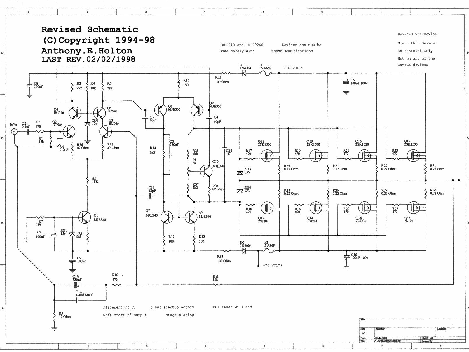
Younger student brother will take an interest to do electronics project sends a teacher. Then come to consult with me. He wants to build Mosfet power Amplifier 300W rms model the stereo Amp. Which be the character OCL the sound is good. I then try to seek the circuit gives him sees in rows the way , accidentally meet this circuit. which design by Anthony.E.Holton. He designs this circuit well. Use power 2SK1530+2SJ201 MOSFET x 4 jigsaw puzzle parallel amounts. make have power amplify tall arrive at about 300W rms true power FULL watt. Detail other part want friends see in original circuit.

120W MOSFET power amplifier by IRF540-IRF9540

Friends many you may admire MOSFET power amplifier, because of good sound and durable. Today I begs for to advise 120W MOSFET power amplifier by IRF540 and IRF9540 the circuit are the character of main Amp, Build not difficult , because of use power Supply Voltage lowness about +35V GND -35V. but use current about 3A circuit character cheap very is OCL Amplifier Class AB then good moderately sound. And systematically protect fully both of protect through the circuit a loudspeaker is damaged and other. When see the circuit has already use moderately equipment then not convenient for a novice , but still use in rows building meditation and check to repair MOSFET power amplifier. The circuit is other , get please sir.