Showing posts with label 2N3055. Show all posts

IC 4047 + 2N3055 with PCB Inverter 100W

This circuit power Inverter 100W, so input voltage 12V (battery 12V)
to output volt 220V ac 50HZ, it is asy circuit because less component to use.
It use IC 4047 Squarewave Oscillator 50HZ and
Power Transistor 2N3055 x 2 For driver transformer 220V ac to OUTPUT Power 100W min.

Circuit Inverter 100W by IC 4047 + 2N3055

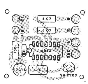
PCB Inverter 100W by IC 4047 + 2N3055
Source: 97 Electron Circuit

NE555 & 2N3055 Inverter 12V to 220V 300W


Inverter 12V to 220V 300W by NE555,2N3055
This be inverter circuit the size about 300W .It performs to transform from battery 12V be house electric 220V 50Hz
by have signal picture is Square wave. And it has the distinction that uses the equipment seek easy, such as integrated
circuit NE555 and 2N3055 transistors. request to have fun circuit this idea

2N3055 Integrated power amplifier OTL 35w circuit and explanation

Friends you many may like Older power amplifier Circuit. Today I begs for to advise Integrated power amplifier OTL 35w by 2N3055. Be interesting circuit because moderately sound 35Watt at 8 ohm loudspeakers from the circuit thinks. Be model OTL then build easy ,economize and durable. Besides still have a button fines to decorate the sound fully such as , Volume,Bass,Treble ,MID Range etc. Then convenient for you who are a novice want to build power amp circuit. Keep use by oneself and I has model PCB simplely give friends. Get convenient in building with Have a good time. With the sound of music please sir.

by 2N3055 Power Supply Voltage Adapter for Car

A car voltage generally is 12 Volts. How about when you want to connect non 12 volts devices into your car? The circuit here is the solution. Even the circuit is design for a car apppliance, it does not seem it can’t be used for another purpose.


Source : http://www.geocities.com/dsaproject/electronics/cook-book/cook-book.html

IC 741, 2N3055 Power Amp OCL 70w

Younger brothers and sisters a student takes an interest to build electronics project sends a teacher. I then choose this circuit , because build easy be valuable certainly. It is Main Power Amplifier Circuit 70Watt RMS sizes are model OCL Class AB. Use pillar equipment be IC 741 and Transistor 2N3055,MJ2955 a little this equipment circuit. If friends want get electric tall power about 70Watt should use Voltage Supply +38V , and -38V. The usability should fine VR1 be appropriate. Request a friend has fun to listen the music from Amp Circuit , please sir.

2N3055 and LM723 + Power Supply 13.8Volt 10Amp circuit

My Friend want circuit power supply for VR.
I Find Website many, See to this Web http://www.rason.org
Good Site circuit.
This is circuit Power Supply 13.8 Volt 10 Amp by LM723 .
Detail ::

This circuit uses the LM723 IC which gives us excellent voltage regulation. The circuit uses 3 pass transistors which must be heat sinked. Resistor R9 allows the fine tuning of the voltage to exactly 13.8 volts and the resistor network formed by resistors R4 through R7 controls the current limiting. The LM723 limits the current when the voltage drop across R5 approaches .7 volts. To reduce costs, most commercial units rely on the HFE of the pass transistors to determine the current limiting. The fault in that system is that the HFE of the pass transistors actually increases when the transistors heat up and risks a thermal runaway condition causing a possible failure of the pass transistors. Because this circuit samples the collector current of the pass transistors, thermal runaway is not a problem in this circuit making it a much more reliable power supply.
Read More in web http://www.rason.org/Projects/powsupply/powsupply.htm

NE540 anb 2N3055 circuit Power Amplifier OCL 35W

Power Amplifier OCL 35W By NE540+2N3055, MJ2955
Power Supply Voltage +25V/-25V 2A.
Output 8 OHM Speaker.
Today have Older power Amplifier OCL Circuit come to give friends get see in rows the way again. By it has the electric power about 35W at 8ohm loudspeakers and use Voltage Supply +25V and -25V at Current 2A. Which cheap systematize the sound is Class AB. By this circuit use the integrated circuit number NE540 replace the transistor has many. Then use power Transistor 2N3055 and MJ2955 at output. The detail is other invite a friend has seen in the circuit , be lucky sir.

2N3055 Circuit Power Amplifier OTL 50W circuit and explanation

If you are seeking power Amplifier at loud good sound , durable and economize. I begs for to advise Circuit Power Amplifier OTL 50Watt by 2N3055 , because of use the equipment that seek good easy and build not difficult with. Many you who tell amp OTL the sound is not good. Me chest edge that be not the loud sound is excellent. Then like to use general ( in the past ) although in contain divide still have use. I like it fining decorates the circuit. Just you feed power supply 50V 2A also the work has already and a loudspeaker should use 8ohm 12 inc. sizes. Besides still model PCB for the convenience of friends. Request have fun Power Amplifier OTL 50Watt , please sir.

LM317 and 2N3055 power supply regulatable 0-28V 20 Amp

Power supply regulatable 0-28V 20Amp
Part list for 20 Ampere regulatable power supply:


Part list for 20 Ampere regulatable power supply:
  • 2 x 15 volt 20+- amps
  • D1…D4= Bridge rectifier MB2504 (25 amps cooled) or eight BYW29 8 amp diodes (TO220 pinning cooled)
    or 8 x MR750 (MR7510) diodes (MR750 = 6 Ampere diode) or 16 x 1N5401 (1N5408) diodes.
  • F1 = 2 Amp
  • F2 = 25 amp
  • R1 2k2 2,5 Watt
  • R2 240 ohm
  • R3,R4,R5,R6 0.1 ohm 10 watt
  • R7 6k8
  • R8 10k
  • R9 47 Ohm 1 watt
  • S2 mini switch
  • R10 8k2
  • C1,C7,C9 47nF
  • C2 four times 4700uF/50v or one 22000uF/50v
  • C3,C5 10uF/50v
  • C4,C6,C9 100nF
  • C8 330uF/50v
  • C10 1uF/16v
  • D5 1N4151
  • D6 1N5401
  • D10 MR750
  • D11 LED
  • D7, D8, D9 1N4001
  • IC1 LM317
  • Two 2N3055 transistors
  • P1 5k
  • P3 10k trimmer
  • relay = 30 volts AC, 2×10 amp switching
S2 switches between +- 3 Amps and full output current
The relay is used to switch off the power supply voltage when the mains (S1) are/is switched off. So no delay do to the discharge of C2, and so preventing output voltages from not return to zero immediately.
A MB2504 is used as it is a 25 ampere rectifier bridge which also should be cooled. Or you could use eight BYW29 8 amp diodes (TO220 pinning) mounted on a heat sink.
Mount a little heatsink on the LM317 IC
Remember to isolate the 2N3055 transistors from the chassis/radiator! Use a radiator (heat sink) of appropriate size and surface area; insulating and heat-conducting spacer or at least a thin mica; hot adhesive and thermal paste.
Source :http://users.belgacom.net/hamradio/schemas/6-20amps_regulatable_powersupplies_on6mu.htm
Thank you.

2N3055 with PCB Power Amplifier OCL 60W

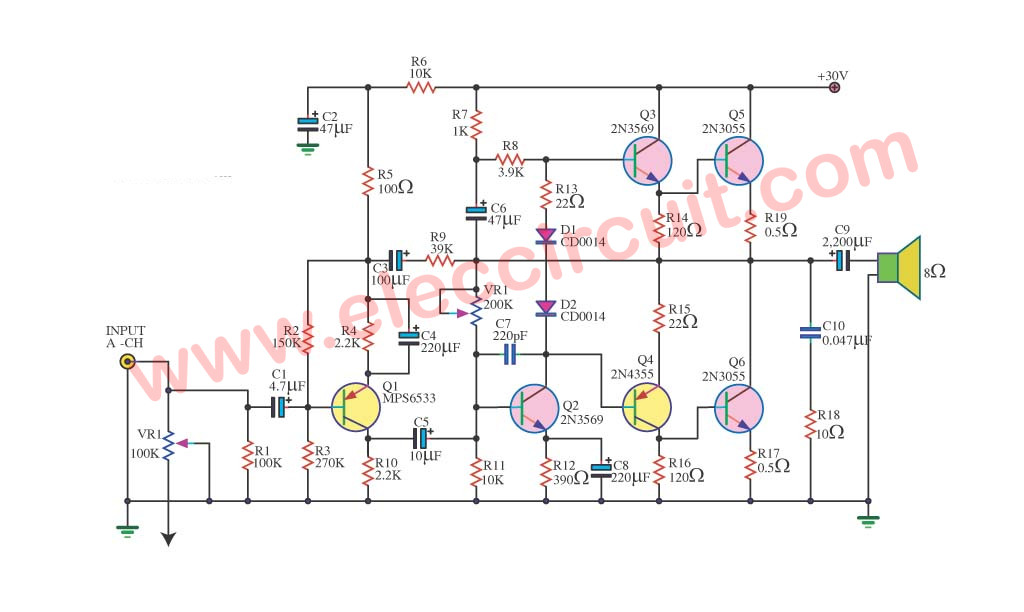
This is Power Amplifier OCL 60W circuit. It is the circuit that gives bland excellent sound , because of use the transistor entirely (Hot part 2N3055 x 2) have no IC mix. Then may build difficult go to small but for what is the experienced person may have no a problem. For sound power that pay to come out about 60W at 8ohm size loudspeakers s build to sing can bail 12 inch sizes comfortablely. About story of the voltage supply for this circuit as a result the important. Should use the pressure about +/- 40V the trend doesn’t lower 3A .Other detail see in circuit picture.

2N3055 and 748 Regulator 15V 400mA circuit and explanation


Regulator 15V 400mA by 748 and 2N3055
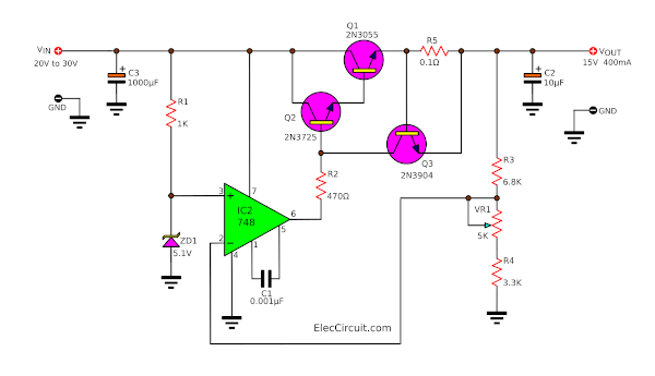
Today try come to see linear regulator 15volt 400mA Circuit. It is use IC op-amp IC748 perform control Voltage Regulator 15V. by have ZD1 5.1V be the referable voltage. For Transistor 2N3055 , perform enlarge current tallly go up and Q3-2N3904 help protect something through the circuit. This circuit can give Current get about 400mA only. Be regarded as the circuit experiences that interesting help give understand the system Voltage Regulator well. The detail is other , a friend has seen in the circuit please sir.

2N3055 with PCB Power Amplifier OCL 60W

This is Power Amplifier OCL 60W circuit. It is the circuit that gives bland excellent sound , because of use the transistor entirely (Hot part 2N3055 x 2) have no IC mix. Then may build difficult go to small but for what is the experienced person may have no a problem. For sound power that pay to come out about 60W at 8ohm size loudspeakers s build to sing can bail 12 inch sizes comfortablely. About story of the voltage supply for this circuit as a result the important. Should use the pressure about +/- 40V the trend doesn’t lower 3A .Other detail see in circuit picture.

2N3055 and LM317 power supply regulatable 0-28V 20 Amp


Part list for 20 Ampere regulatable power supply:

  • 2 x 15 volt 20+- amps
  • D1…D4= Bridge rectifier MB2504 (25 amps cooled)

    or eight BYW29 8 amp diodes (TO220 pinning cooled)
    or 8 x MR750 (MR7510) diodes (MR750 = 6 Ampere diode) or 16 x 1N5401 (1N5408) diodes.

  • F1 = 2 Amp
  • F2 = 25 amp
  • R1 2k2 2,5 Watt
  • R2 240 ohm
  • R3,R4,R5,R6 0.1 ohm 10 watt
  • R7 6k8
  • R8 10k
  • R9 47 Ohm 1 watt
  • S2 mini switch
  • R10 8k2
  • C1,C7,C9 47nF
  • C2 four times 4700uF/50v or one 22000uF/50v
  • C3,C5 10uF/50v
  • C4,C6,C9 100nF
  • C8 330uF/50v
  • C10 1uF/16v
  • D5 1N4151
  • D6 1N5401
  • D10 MR750
  • D11 LED
  • D7, D8, D9 1N4001
  • IC1 LM317
  • Two 2N3055 transistors
  • P1 5k
  • P3 10k trimmer
  • relay = 30 volts AC, 2×10 amp switching

S2 switches between +- 3 Amps and full output current

The relay is used to switch off the power supply voltage when the mains (S1) are/is switched off. So no delay do to the discharge of C2, and so preventing output voltages from not return to zero immediately.

A MB2504 is used as it is a 25 ampere rectifier bridge which also should be cooled. Or you could use eight BYW29 8 amp diodes (TO220 pinning) mounted on a heat sink.

Mount a little heatsink on the LM317 IC

Remember to isolate the 2N3055 transistors from the chassis/radiator! Use a radiator (heat sink) of appropriate size and surface area; insulating and heat-conducting spacer or at least a thin mica; hot adhesive and thermal paste.

Source :http://users.belgacom.net/hamradio/schemas/6-20amps_regulatable_powersupplies_on6mu.htm
Thank you.

2N3055 and 741 power supply 20A 13.8V


This be high current power supply circuit , Which there is the size voltage 13.8V at 20A.By it uses base equipment that seeks to buy easy, be integrated number circuit LM741 perform maintain one’s position voltage be stable or Regulated at 13.8V. Which can fine can decorate a little again. Besides still have the power transistors 2N3055 X4 numbers bring to build parallel perform enlarge current tall arrive at 20Amp Other detail , see in the circuit.

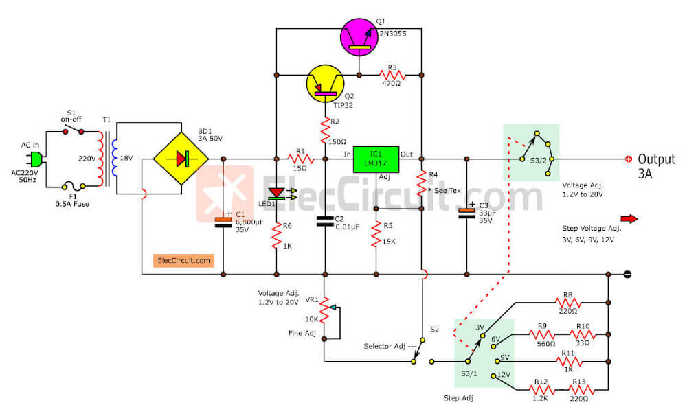
2N3055 + LM317T power supply regulator 1_2V-20V & 3V-6V-9V-12V 3Amp


This is Circuit Power supply regulator Current 3Amp Voltage output : 1.2V-20V and 3V,6V,9V,12V.
Use IC LM317T and 2N3055, Easy to Bulid and normal part low cost too. detail see in circuit image.

2N3055 and LM723 variable 3V – 18V 10amp Power Supply


Had a need for a low voltage power supply today with high current, and since it was after 530 and tommorrow being Sunday, I decided to build one. So I got a few parts that I had laying around and built it. Except for the 15 amp transformer, 50 amp bridge and 40,000 Ufd capacitor, I figure the parts would cost about 3 or 4 bucks. The supply is ROCK stable and variable from 3 volts to 18 volts. The supply is over voltage and over current protected as a bonus. See figure below.

Read more Source:

http://www.anatekcorp.com/ttg/tiptrick.htm#10%20amp%20Power%20Supply

2N3055 Variable DC Power Supply circuit and explanation

Voltage range: 0.7 – 24V Current limiting range: 50mA – 2A

A Variable DC Power Supply is one of the most useful tools on the electronics hobbyist’s workbench. This circuit is not an absolute novelty, but it is simple, reliable, “rugged” and short-proof, featuring variable voltage up to 24V and variable current limiting up to 2A. Well suited to supply the circuits shown in this website. You can adapt it to your own requirements as explained in the notes below.
Notes:

* P1 sets the maximum output current you want to be delivered by the power supply at a given output voltage.
* P2 sets the output voltage and must be a logarithmic taper type, in order to obtain a more linear scale voltage indication.
* You can choose the Transformer on the grounds of maximum voltage and current output needed. Best choices are: 36, 40 or 48V center-tapped and 50, 75, 80 or 100VA.
* Capacitor C1 can be 2200 to 6800µF, 35 to 50V.
* Q4 must be mounted on a good heatsink in order to withstand sustained output short-circuit. In some cases the rear panel of the metal box in which you will enclose the circuit can do the job.
* The 2N3055 transistor (Q4) can be replaced with the slightly less powerful TIP3055 type.

Parts:
P1____________500R Linear Potentiometer
P2_____________10K Log. Potentiometer
R1,R2___________2K2 1/2W Resistors
R3____________330R 1/4W Resistor
R4____________150R 1/4W Resistor
R5______________1R 5W Resistor
C1___________3300µF 35V Electrolytic Capacitor (see Notes)
C2______________1µF 63V Polyester Capacitor
D1,D2________1N5402 200V 3A Diodes
D3_____________5mm. Red LED
Q1____________BC182 50V 100mA NPN Transistor
Q2____________BD139 80V 1.5A NPN Transistor
Q3____________BC212 50V 100mA PNP Transistor
Q4 __________2N3055 60V 15A NPN Transistor
T1_____________220V Primary, 36V Center-tapped Secondary
50VA Mains transformer (see Notes)
PL1____________Male Mains plug
SW1____________SPST Mains switch

Read More Source: http://www.redcircuits.com//Page36.htm
Thank you.

2N3055 and LM723 3-30 V/2.5 A Stabilized power supply


This is a very useful project for anyone working in electronics. It is a versatile power supply that will solve most of the supply problems arising in the everyday work of any electronics work shop. It covers a wide range of voltages being continuously variable from 30 V down to 3 V. The output current is 2.5 A maximum, more than enough for most applications. The circuit is completely stabilised even at the extremes of its output range and is fully protected against short-circuits and overloading.

——————————————————————————–
Technical Specifications – Characteristics
Input voltage: 24V DC
Output current: 2.5 A
Output volytage: 3-30V DC
——————————————————————————–

How it Works
The power supply is using a well known and quite popular VOLTAGE STABILIZER IC the LM 723. The IC can be adjusted for out put voltages that vary continuously between 2 and 37 VDC and has a current rating of 150 mA which is of course too low for any serious use. In order to increase the current handling capacity of the circuit the output of the IC is used to drive a darlington pair formed by two power transistors the BD 135 and the 2N3055. The use of the transistors to increase the maximum current output limits the range of output voltages somewhat and this is why the circuit has been designed to operate from 3 to 30 VDC. The resistor R5 that you see connected in series with the output of the supply is used for the protection of the circuit from overloading. If an excessively large current flows through R5, the voltage across it increases and any voltage greater than 0.3 V across it has as a result to cut the supply off, thus effectively protecting it from overloads. This protection feature is built in the LM 723 and the voltage drop across R5 is sensed by the IC itself between pins 2 and 3. At the same time the IC is continuously comparing the output voltage to its internal reference and if the difference exceeds the designer’s standards it corrects it automatically. This ensures great stability under different loads. The potentiometer P1 is used to adjust the out put voltage at the desired level. If the full range from 3 to 30 V is desired then you should use a mains transformer with a secondary winding having a rating of at least 24 V/3 A. If the maxi mum voltage output is not desired you can of course use a transformer with a lower secondary voltage output. (However, once rectified the voltage across the capacitor C2 should exceed by 4-5 volts the maximum output expected from the circuit.
Parts List
R1 = 560R 1/4W C1 = 100nF
R2 = 1,2 K 1/4W C2 = 2200uF 35-40V
R3 = 3,9 K 1/4W C3 = 100 pF
R4 = 15K 1/4W C4 = 100uF/ 35V
R5 = 0,15R 5W

D = B40 C3300/2200, 3A rectifier bridge
P1 = 10K potesiometer TR1 = BD 135
IC = LM723 TR2 = 2N3055

Read More Source: http://www.uashem.com/pageid-215.html
Thank you.

LM723,CA3140,2N3055 Variable Regulator 0-30V 5A

Circuit_Variable Regulator 0-30V 5A lm723_ca3140_2n3055

This is circuit Variable Regulator power supply,Output voltage 0-30V and Current 5A max. Use IC LM723 is a voltage regulator designed primarily for series regulator applications. By itself, it will supply output currents up to 150 mA I so use Transistor 2N3055 X 2 for Booster current to 5A. IC CA3140 for Control Current and Voltage.
P1-50K for control current.
R20-50K for Adjustable voltage output.
R19-5K for fine Adjustable voltage output.
Transformer use 5-8A, Voltage see in circuit.
Detail more see circuit.

PCB Variable Regulator 0-30V 5A by LM723,CA3140,2N3055
PCB Variable Regulator 0-30V 5A

2N3055 , TL431 Regulator 5VDC 200mA


Source : joe (aircraftdesigner)
Here is circuit power supply regulator 5VDC 200mA.
it easy linear supply circuit with Transistor 2N3055 and IC TL431