Showing posts with label Phone. Show all posts

Telephone line monitor Telephone line monitor If you feel that somebody is tampering with your telephone line you might find this little circuit

Telephone line monitor

Telephone line monitor

If you feel that somebody is tampering with your telephone line you might find this little circuit useful. It detects if there is another telephone connected to the line, if there is a short or an open line. Sound and a flashing light will tell you which is the current situation. The speaker is practically cut out during a normal conversation thus preserving privacy, only the LED will flash occasionally. The circuit does not require any battery and takes the supply from the telephone line itself. The transistors used are wired in a reversed biased fashion thus behaving as oscillators. You might try the 2N2222A as an alternative (not tested). This monitor is, of course, suitable only for analogue lines. Watch the polarity of the input line: the circuit will not be damaged by a polarity reversal but it will not operate correctly.

Cut Phone Line Detector A while ago I got an email asking for the schematic of a circuit to detect cut phone

Cut Phone Line Detector

A while ago I got an email asking for the schematic of a circuit to detect cut phone lines. It didn't take me long to find this circuit in Electronics Now. When the circuit detects that a phone line has been cut, it activates a MOSFET which can be used to drive a relay, motor, etc. It can also be connected to a security system.

Schematic


This is the schematic of the cut phone line detector

Parts


Part

Total Qty.

Description

Substitutions

R1, R2, R3

3

22 Meg 1/4 W Resistor


R4

1

2.2 Meg 1/4 W Resistor


C1

1

0.47uF 250V Mylar Capicitor


Q1

1

2N3904 Transistor

2N2222

Q2

1

2N3906 Transistor


Q3

1

IRF510 Power MOSFET


D1

1

1N914 Diode


Load

1

See "Notes"


MISC

1

Wire, Phone Connectors, Circiut Board


Notes

1. The "Load" can be a relay, lamp, motor, etc. The circuit can also be connected to a security system to sound an alarm in case the phone line is cut.

2. If the circuit is connected to a security system or other circuit, both circuits must be electrically isolated from each other using an opto-isolator, relay, etc. This also means that the Cut Phone Line Detector must be powered by a seperate 9V supply.

Soft Musical Telephone Ringer The normal telephone bell, at times (specially during night when one does not want to be disturbed), appears to be

Soft Musical Telephone Ringer

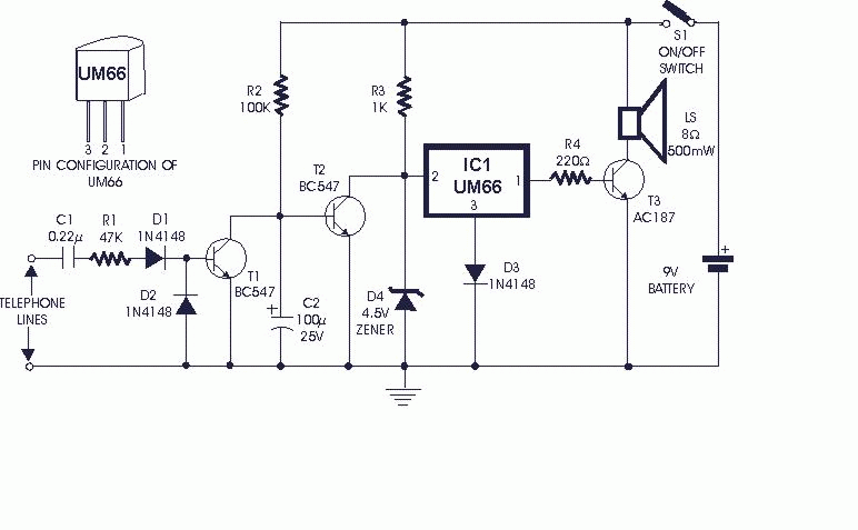
The normal telephone bell, at times (specially during night when one does not want to be disturbed), appears to be quite irritating. The circuit shown here converts the loud sounding bell into a soft and pleasing musical tone.


The incoming ring is detected by transistor T1 and components wired around it. In absence of ringing voltage, transistor T1 is cut off while transistor T2 is forward biased as resistor R2 is returned to the positive supply rails. As a result collector of transistor T2 is at near-ground potential and hence IC1 (UM66) is off. Also capacitor C2 is charged to a slightly positive potential.


During positive half of the ringing voltage, diode D1 forward biases transistor T1 and rapidly discharges capacitor C2 to near ground potential and cuts off transistor T2 which, in turn, causes IC1 to be forward biased and music signal is applied to base of transistor T3 which drives the speaker. During negative half of the ringing voltage, capacitor C2 cannot charge rapidly via resistor R2 and hence transistor T2 remains cut off during the ringing interval. Thus the soft musical note into the loudspeaker sounds in synchronism with the ringing signal. When handset is lifted off the cradle, the ringing voltage is no more available and hence the soft musical note switches off.

Soft Musical Telephone Ringer

Click on the image to view the full

Phone "Hold" With Music Phone Hold With Music This circuit will allow you to place a phone call on hold and if you wish to have them listen to mu

Phone "Hold" With Music

Phone Hold With Music

This circuit will allow you to place a phone call on hold and if you wish to have them listen to music while they are on hold. The circuit operates as follows: The RED wire from the phone jack is typically positive and the GREEN wire is negative or ground. When you want to place a call on hold, close S1 and hang up the handset. The resistor R1 simulates another phone off hook and allows enough

current to pass through to prevent the phone company from disconnecting the call. The resistor R2 and LED provide a visual indication that you have someone on hold ( this is optional )

The capacitor C1 and the transformer provide the interface to a radio or CD player headphone jack. Before you hook up the project to the phone line you must determine the polarity of the line. Place a voltmeter across the red and green wires of the telephone line, there should be about 48 volts

DC positive when the black lead of your meter is connected to the green phone wire. If it is negative 48 volts then reverse the wires.

Phone line indicator With this circuit you can monitor your telephone line. You are able to detect if any telephone in the same line is busy w

Phone line indicator

With this circuit you can monitor your telephone line. You are able to detect if any telephone in the same line is busy with the help of a LED. This circuit does not affect the telephone's line provider, so it's trouble free but you use it at your own risk.

It connects in parallel with the telephone line. The bridge rectifier (D1...D4) at the input protects the circuit from reverse polarity. When none of the telephones of this line is used then the voltage across the line is about 50-60V. This voltage with the help of the bridge and R1/R2 voltage divider affects the gate of BF256B so it stays in non conductive mode. When a telephone is used the voltage across the line drops suddenly and Ô1 goes to conductive mode so the Led lights up, giving us the "in use indication".

Phone line indicator

In Ô1 the current which flows through LED is about 10mÁ. The zener diode D5 prevents gate's voltage to excess 10V and C1 works like a filter for unwanted pulses. If your circuit doesn't work ok , you can replace R1 with another, but no more that a 220ÊÙ one.

The circuit works ok with a 9V battery and you can put it into a plastic box.
Attention:
50V from the telephone line can become dangerous under some circumstances so take precautions when handling it.

PCB

telephone2-2.gif telephone2-3.gif

Parts List

R1= 100K
R2= 1M
C1=1ì/63V
T1=BF256B
D1..D4=1N4004
D5= 10V/1W
D6=Led red