Showing posts with label Other. Show all posts

Transistor Appearance circuit and explanation

    The outward appearance of the transistor varies. Here, two kinds are shown.


On the left in the photograph is a 2SC1815 transistor, which is good for use in a digital circuit. They are inexpensive when I buy them in quantity. In Japan it costs 2,000 yen for a pack of 200 pieces. (About 10 US cents/piece in 1998)

On the right is a device which is used when a large current is to be handled. Its part number is 2SD880.


The electrical characteristics of each is as follows.

Item2SC18152SD880
VCEO(V)5060
IC(mA)1503A
PC(mW)40030W
hFE70 - 70060 - 300
fT(MHz)803


VCEO:The maximum voltage that can be handled across the collector(C)
and emitter(E) when the base(B) is open. (Not connected)
(It may be shown as VCE)
IC:The maximum collector(C) current.
PC:Maximum collector(C) loss that continuously can cause it consumed
at surroundings temperature (Ta)=25°C
(no radiator)
hFE:The current gain to DC at the emitter(E).
(IC/IB)
fT:The maximum DC switching frequency. (the transision frequency)


Data sheet for 2SC1815

IC LM3915 Audio Spectrum Analyzer Mini Circuit and explanation


The circuit has been designed to create a spectrum analyzer that will provide an analysis of a sound to determine at various frequencies, the volume of sounds that make up the overall sound spectrum.
Circuit Explanation
The device is sensitive enough to determine the sound wave components of frequency and amplitude with the changing of frequency and the width of an acoustic signal. The proportionality of signal width is indicated by the brightness of LED as it turns ON while the color indicates the proportionality of frequency. In order for the red LED to turn ON in strong signal, the sensitivity of the input circuit is adjusted by resistor R2. The middle signal is represented by a yellow LED while the low signal is indicated the green LED.
The 10 LEDs in 3 lines comprise the display unit which is ensured the IC2 as it functions as a counter decoder represented by the two gates ICa-b.the frequencyof the counter is being regulated by R6. No LED will turn ON in the absence of any signal in the input. The LEDs will begin to flicker or blink depending on the intensity and tempoof the signal, once a signal has been applied in the input. The values of the resistors R4 & R5 can be varied that will be suitable for the desired requirements. Alternatively, this can be done by placing a 1K ohm trimmer in place of R4 & R5 during the initial regulation and adjustmentof the values. It can be eventually removed and replaced with permanent resistors as soon as the desired values are achieved. Additional LEDs can be added in connection to IC2 although this circuit does not precisely measure the input signal.
Part List
R1= 1K8Kohm
R2= 100Kohm trimmer
R3= 1Kohm
R4= 100 ohm…..1Kohm
R5= 100 ohm…..1Kohm
R6= 100Kohm trimmer
C1= 100nF 100V
D1….10= RED LED
D11….20= YELLOW LED
D21….30= GREEN LED
IC1= LM3915
IC2= 4017
IC3= 4011
Application
This audio spectrum analyzer is a user interface component capable of making visible the sound pressure for a range of frequencies over time by taking a sample from an audio data stream and an animated visualization during the play is created in real time. It is ideal for any purpose which includes analysis and identification of human speech, ham radio audio reception tuning, analysis of vocal and instrumental music, evaluation and tuning of musical instruments, analysis of bat echolocation sounds, evaluation and calibration of home audio systems, and analysis and identification of biological sounds. Other uses of the audio spectrum analyzer are in distortion analysis, transfer functions, and digital filtering.
Source: Mini Spectrum Analyzer for Audio/Sound by LM3915

Regulator Solar Cell Voltage Regulator circuit and explanation

This device is designed to be a simple, inexpensive ‘comparator’, intended for use in a solar cell power supply setup where a quick ‘too low’ or ‘just right’ voltage indicator is needed. The circuit consists only of one 5V regulator, two transistors, two LEDs, five resistors, two capacitors, and one small battery. Although a 4-V battery is indicated, 4.5 V (3 alkalines in series) or 3.6 V (3 NiCd cells in series) will also work.
The specifications of voltage regulator IC1 are mainly determined by the size and number of the solar cells and the current pull of the equipment connected to the output. Here the low-drop 4805 is suggested but other regulators may work equally well as long as you observe the output voltage of the solar cells. Transistors T1 and T2 are complementary types i.e. one each of the pnp and npn variety.
Circuit diagram:
solar cell voltage regulator circuit schematic
Solar Cell Voltage Regulator Circuit Diagram
Although the ubiquitous BC557B (pnp) and BC547B (npn) are indicated, any small-signal equivalents out of the junk box will probably do. The values of voltage dividers R1/R6 and R3/R4 may need to be adjusted according to the type of transistor and its gain, or according to the desired voltage thresholds. Using the resistor values shown in the schematic, LED D2 turns on fully when the voltage is just above 5 volts.
LED D1 turns on when the voltage drops below 4.2 volts or so. Between those two thresholds, there is a sort of no man’s land where both LEDs are on dimly. A buzzer or other warning device could be connected across the terminals of LED D1 to give a more substantial warning if the voltage drops below operating limits. The current consumption ofthe circuit is about 20 mA at 5 V, and it decreases with the voltage supplied by the solar cells.
Reuben Posthuma
http://www.extremecircuits.net/2010/05/solar-cell-voltage-regulator.html

1.5 Volt Tracking Transmitter


The current draw for this tracker is 3.7mA, so the 1.5V button cell will last awhile. What the heck am I suppose to hear you ask? When your circuit is working you should see the LED flash quite fast. Take your FM radio and search for the low-beat ‘humbe-humbe-humbe-etc’ equal to the flash of the LED (probably around the 100Mhz). Found it? If that position is interferering with a radio station you can fine-tune it with the variable capacitor. If you like to have the tracker around the 88Mhz you can do that by spreading the windings from the home-made coil just a bit (1/2 a millimeter or so). Anyways, play with it and learn. It is a nice project. The 12-inch antenna can be anything, it is not really that critical. I used a piece of 22 gauge flexible wire. I haven’t checked the range but will do that shortly.

* For stability, use a NPO types for C2 & C4.

* Resistance tolerance for R1 should be 1 or 2%.

* Frequency range is the usual 87-109Mhz on the FM dial.

* The coil is made from 22 ga ‘hookup’ wire, like the solid Bell phone wire. Leave the insulation on.

* The LED is the ‘High Brightness’ type for maximum illumination.

source electro-tech-online .com

Home Wiring Installation, Testing and Troubleshooting – a Complete Guide eBook

The following ebook you will find, provides a comprehensive manual for home wiring system from basic repairs to advanced projects.

home wiring installation ebook This ebook manual is divided into sections covering topics on Planning a Wiring Project, Circuit Maps for Common Wiring Layout, Basic (covers discussion on tools, materials and technique, electrical boxes for projects, installing electrical boxes, wires and cables for projects, installing NM cable, Conduit, Circuit Breaker Panels, Connecting Circuit Breakers, installing outdoor wiring, mounting the distribution centers, routing cables and wires, installing an , making final connections, testing the system and troubleshooting problems etc. Here is a quotation from the ebook:

An electrical circuits is a continuous loop. Household circuits carry power from the main service panel, throughout the house, and back to the main service panel. Several switches, receptacles, light fixtures, or appliances may be connected to a single circuit. Current enters a circuit loop on hot wires and returns along neutral wires. These wires are color coded for easy identification. Hot wires are black or red, and neutral wire are white or light gray.

Find more information about Home Wiring Installation, Testing and Troubleshooting - a Complete Guide eBook in the following Complete Guide to Home Wiring Diagram.

Electrical Wiring for Building – Standard and Code

Electrical Wiring Standard and Code Here is an article discuss on Electrical Wiring Standard and Code as used to provide power in buildings and structures, commonly referred to as building wiring.

The international standard wire sizes are given in the IEC 60228 standard of the International Electrotechnical Commission. This document and its precursors were created due to a need for a standard definition of cable conductor size. However, this standard is not written in such language that it can readily be adapted as a national wiring code.

Get more information regarding the Electrical Wiring Standard and Code here (reference: scribd.com)

Typical Throttle Position Sensor Circuit Diagram

Here is a typical schematic diagram of the car Throttle Position Sensor Circuit. The Throttle Position Sensor (TPS) is designed to indicates the position of the throttle valve. Usually the Throttle Position Sensor is mounted on the throttle body and converts the throttle valve angle into an electrical signals. Inside the TPS is a resistor and a wiper arm. The arm is always contacting the resistor.
 Throttle Position Sensor Circuit Diagram
How the Throttle Position Sensor works?
A wiper arm inside the sensor is mechanically connected to a moving part, such as valve or vane. As the part moves, the wiper arm also moves. The wiper arm is also in contact with a resistor. As the wiper arm moves on the resistor, the signal voltage output changes which indicates position.

IC NE5532 x2. Tone Control Stereo (bass-treble)


LMD18245 , 3A, 55V DMOS Full-Bridge Motor Driver features and overview

Features


  • DMOS power stage rated at 55V and 3A continuous
  • Low RDS(ON) of typically 0.3 per power switch
  • Internal clamp diodes
  • Low-loss current sensing method
  • Digital or analog control of motor current
  • TTL and CMOS compatible inputs
  • Thermal shutdown (outputs off) at TJ = 155°C
  • Overcurrent protection
  • No shoot-through currents
  • 15-lead TO-220 molded power package
  • Description

    The LMD18245 full-bridge power amplifier incorporates all the circuit blocks required to drive and control current in a brushed type DC motor or one phase of a bipolar stepper motor. The multi-technology process used to build the device combines bipolar and CMOS control and protection circuitry with DMOS power switches on the same monolithic structure. The LMD18245 controls the motor current via a fixed off-time chopper technique.

    An all DMOS H-bridge power stage delivers continuous output currents up to 3A (6A peak) at supply voltages up to 55V. The DMOS power switches feature low RDS(ON) for high efficiency, and a diode intrinsic to the DMOS body structure eliminates the discrete diodes typically required to clamp bipolar power stages.

    An innovative current sensing method eliminates the power loss associated with a sense resistor in series with the motor. A four-bit digital-to-analog converter (DAC) provides a digital path for controlling the motor current, and, by extension, simplifies implementation of full, half and microstep stepper motor drives. For higher resolution applications, an external DAC can be used.


    Applications

  • Full, half and microstep stepper motor drives
  • Stepper motor and brushed DC motor servo drives
  • Automated factory, medical and office equipment
  • to download the datasheet and for readmore on this article follow the link
  • http://www.national.com/mpf/LM/LMD18245.html#Overview
  • LASCR-Light Activated SCR circuit

    LASCR or Photo SCR

    LASCR or Photo SCR

    Light activated SCR (LASCR) or a Photo SCR is just an ordinary SCR except that it can also be light triggered. Most LASCRs also have a gate terminal for being triggered by an elec­trical pulse just as a conventional SCR. The basic construction of an LASCR is shown in figure. The schematic symbols most commonly used for the LASCR are shown in figure. Some LASCRs have clear windows in their cases so that light sources from other devices can be cou­pled to them. Many have the light source encapsu­lated in the same package so that a relay is formed. When the light falling on depletion layers is strong enough, valence electrons are dislodged from their orbits and become free electrons. When these free electrons flow out of the collector of one, transistor into the base of the other.

    LASCR Symbol

    LASCR Symbol

    The positive feedback starts and the LASCR turns on just like a normal SCR, the LASCR will continue to conduct even if the light source is removed. For maximum sensitivity to light, the gate is left open, as shown in figure. Trigger adjust can be included if an adjustable trip point is desired as shown in figure. The gate resistor diverts some of the light produced electrons and alters the sensitivity of the circuit to the incoming light. The devices are for low power applications.

    LASCR Applications

    The LASCRs find many applications including optical light controls, relays, phase control, motor control and a large number of computer applications. The maximum current (rms) and power (gate) ratings for LASCRs commercially avail-able are about 3 A and 0.1 W. With the increase in junction temperature the light energy required to activate the device is reduced.
    Relay with LASCR

    Relay with LASCR

    Relay using LASCR

    A solid-state relay using two LASCRs in reverse parallel is shown in figure. Two LASCRs are connected in reverse parallel so as to obtain conduction in both half cycles of the applied supply voltage Vg. A single light-emitting diode (LED) is employed for triggering both LASCRs. Bias resistors are used to control the light sensitivity of the gates and avoid sporadic triggering during off periods. Usually all the three active devices (two LASCRs and one LED) and the two bias resistors RG are encapsulated in the same package. Since the relay action does not require direct electrical connection, such relays are often used to couple signals into very high voltage equipment and other dangerous locations.

    Read more: http://www.circuitstoday.com/category/components#ixzz1J7TLQ3i1
    Under Creative Commons License: Attribution

    UJT Characteristics

    UJT Characteristics

    UJT Characteristics

    The static emitter char­acteristic (a curve showing the relation between emitter voltage VE and emitter current IE) of a UJT at a given inter base voltage VBB is shown in figure. From figure it is noted that for emitter potentials to the left of peak point, emitter current IE never exceeds IEo . The current IEo corresponds very closely to the reverse leakage current ICo of the conventional BJT. This region, as shown in the figure, is called the cut-off region. Once con­duction is established at VE = VP the emitter po­tential VE starts decreasing with the increase in emitter current IE. This Corresponds exactly with the decrease in resistance RB for increasing cur­rent IE. This device, therefore, has a negative resistance region which is stable enough to be used with a great deal of reliability in the areas of applications listed earlier. Eventually, the valley point reaches, and any further increase in emitter current IE places the device in the saturation region, as shown in the figure. Three other important parameters for the UJT are IP, VV and IV and are defined below:

    Peak-Point Emitter Current. Ip. It is the emitter current at the peak point. It repre­sents the rnimrnum current that is required to trigger the device (UJT). It is inversely proportional to the interbase voltage VBB.

    Valley Point Voltage VV The valley point voltage is the emitter voltage at the valley point. The valley voltage increases with the increase in interbase voltage VBB.

    Valley Point Current IV The valley point current is the emitter current at the valley point. It increases with the increase in inter-base voltage VBB.

    Special Features of UJT. The special features of a UJT are :

    1. A stable triggering voltage (VP)— a fixed fraction of applied inter base voltage VBB.
    2. A very low value of triggering current.
    3. A high pulse current capability.
    4. A negative resistance characteristic.
    5. Low cost.

    Read more: http://www.circuitstoday.com/category/components#ixzz1J7T15Xs2
    Under Creative Commons License: Attribution

    LM1040 tone control circuit project

    A very simple tone control circuit project can be constructed using this electronic schematic circuit diagram that is based on the LM1040 tone control IC . This tone control electronic schematic is very simple and has many features like : volume control , balance control and loudness function . When adjusted for maximum boost in the usual application circuit, the LM1040 cannot give additional boost from the loudness control with reducing gain. If it is required, some additional boost can be obtained by restricting the tone control range and modifying Ct, Cb, to compensate.

    The typical DC level at pins 3 and 22 is 7.5 V (Vcc= 12V), with the input signal superimposed, and this can be used to bias a FET switch as shown to save components. For switching with a 0V-5V signal a low-threshhold FET is required when using a 12V supply. With larger switching levels this is less critical.
    The high impedance PNP base input of the loudness control pin 9 is readily switched with a general purpose NPN transistor.
    As you can see in the circuit diagram , this electronic schematic has two separate inputs and two outputs and one stereo enhancement switch connection .

    tone control circuit project using LM1040 IC

    6C45Pi Single Ended Class-A Power Amplifier circuit and explanation

    The valve itself, have a simple circuit enviable any transistor amplifier, however, not many projects that employ a single active component. This construction philosophy, I like to call it minimalism.

    If one speaks of minimalism, I think, that this project has all the credentials to qualify as such.

    This is an amplifier cu, a final integrated (Compact) which employs a single tube (triode) signed 6C45Pi. To do this, could be used several tubes, including 437A, E55L (pentode) and the fantastic and expensive EC8020.

    Two lines must for this valve: The EC8020 has an exceptional linearity, high dissipation and trasconduttanza worthy of a power triode. All factors ideal for a good amplifier cu, were it not for the price (on the ebay Offers easily exceed one thousand dollars!).

    6C45Pi even if does not reach the performance of EC8020, performs the task with dignity. The cost is a couple of orders of magnitude lower and is currently produced by Electro Harmonix and is part of his series most valuable the Gold Pins.

    Schematic Diagram

    The circuit used setup is classic: single-ended. This choice leads to a lower power, an output transformer more expensive, but all will benefit, at least for my taste, the sound quality.

    shematic-Single-Ended-Class-A-Power-Amplifier-using-6C45Pishematic-Single-Ended-Class-A-Power-Amplifier-using-6C45Pi

    About nutrition, the first idea was to use, such as straightening, a valve, but with an excessive size of the Schottky diode and filtering capabilities have also obtained excellent results (Sonic).


    PCB

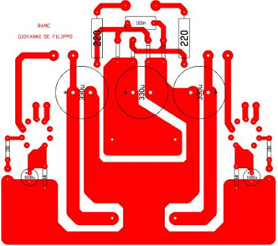
    Not many projects are implemented on printed circuit valve, but it is my strong belief that, 's addition to a more orderly construction, provides added value to the success of the project.

    The layout is as follows:
    PCB-Layout-Single-Ended-Class-A-Power-Amplifier-using-6C45PiPCB-Layout-Single-Ended-Class-A-Power-Amplifier-using-6C45Pi

    A fundamental rule in the design of the board is to avoid any link mass, so you should use as much as possible in a star structure. Usually the star center coincides with the negative of the first capacitor filter.

    Realization

    The board:
    PCB2-Single-Ended-Class-A-Power-Amplifier-using-6C45Pi
    PCB1-Single-Ended-Class-A-Power-Amplifier-using-6C45Pi

    I used the usual method of iron more HCl + H 2 O 2.

    Four resistors are metal film for half a watt, those from 220ohm wire wound vitreous enamel coated 6W, the Panasonic FC Electrolytic low impedance. Alps potentiometer, then the diodes, as already mentioned, type Schottky 1000V 1.5 A.

    The two TU are wrapped by the Company upon specific ATC Electronix: www.atcelectronix.com/ provides the following features:

    Primary: 4000 ohms
    Secondary: 6 ohms
    Power: 10W
    Grain-oriented core AC 0:35
    Bandwidth: 15 Hz - 75 KHz
    trafo-Single-Ended-Class-A-Power-Amplifier-using-6C45Pi


    I like to use for my projects output transformers wound on specific, because I have the opportunity to obtain more than I seek., The kind Mr. E. Calabrese's ATC Electronix has been immediately available, we discussed the characteristics and came quietly meeting.

    Mechanically, the TU are well made, sturdy, beautiful black ice caps, we see that there is the hand of a fan.

    Some photos of finished:
    Single-Ended-Class-A-Power-Amplifier-using-6C45Pi

    The cabinet is birch plywood 10mm polished with wax. I like the effect that old yellow comes out. The photos do not make the idea of greatness, but it is really small, only 230 x 200 mm high 60mm (TU and TA excluded).

    rear-Single-Ended-Class-A-Power-Amplifier-using-6C45Pi

    I suggest to the speaker terminals, derived from a larval bi-wiring connections, it was a very economical way to get the four terminals, buying in bulk would have cost me more.

    inside-Single-Ended-Class-A-Power-Amplifier-using-6C45Pi

    The cable used for connections between RCA, potentiometer and card is excellent Belden.

    Listening

    A valve, one triode and yet it sounds. Thought of having to keep the volume potentiometer can to listen to a decent level, but it was not at all. The pot did not exceed half of the race than I shouted down ... but we are talking about a "paltry" Watts!. Certainly the BLH (FE108ESigma) have done their bit (90 dB / W efficiency).

    I connected everything, turned on and my room was immediately filled with music. Main features: detail, depth and dynamics.

    Everything I heard sounded really good, thanks not only 6C45Pi but also of TU ATC Electronix.

    The Finaly I am deeply moved, usually happens at concerts and my master amplifier.

    The Medes and the voices are spectacular. I listened to all possible kinds of vocal music. Each of them seem natural, male or female is.

    From Jazz to Classical, dall'Acustica the Rock and anything there is in the middle, everything comes back perfect. This little amp is very transparent.

    Having experienced the one-tube amplifier, I had the confirmation: I will be forever minimal! Few watts, or only a few components in the audio chain, single screw speakers, no cross-over, no feedback, just pure music!. An amp like this, a simple player, a pair of single screw is all that a person has (or should have) need. I am extremely satisfied, so much so that I could separate me from my SE with the 2A3 and not feel greatly missed.

    Faults? Sure. The sensitivity is very high, indeed it is low for maximum power output must be driven by almost 5 Vpp. The dynamic is good, but only one watt is just for musicians. However, the little man is promoted with flying colors while remaining down to earth.

    (Source: http://digilander.libero.it/giovannidefilippo/progetti/GDF-UNICO!/UNICO.htm)

    converter circuit Frequency fromLight circuit and explanation

    A simple Light to Frequency Converter

    Introduction.

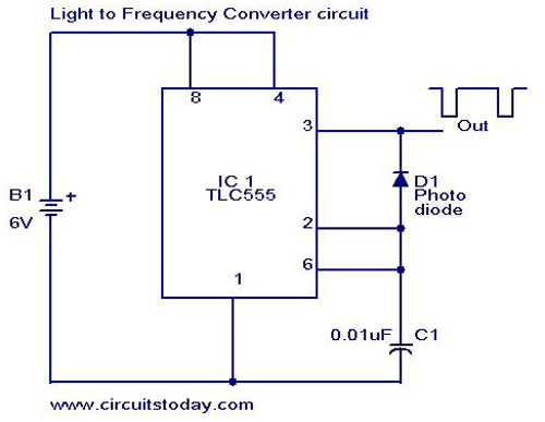
    Here is the circuit diagram of a effective light to frequency converter circuit that can be used for variety of applications such as light intensity measurement,fun etc.

    The circuit is based on TLC555, the CMOS version of famous timer IC NE 555. A photo diode is used for sensing the light intensity.The timer IC is wired in astable mode.The leakage current of the reverse biased photo diode is proportional to the light intensity falling on it.This leakage current charges the capacitance C1.When the capacitor voltage reaches 2/3 of the supply voltage the out put (pin 3) goes low.As a result the capacitor discharges through photo diode .When the capacitor voltage reaches 1/3 the supply voltage the out put (pin 3) of IC goes high.This cycling continues and we get a frequency at pin 3 proportional to the light intensity falling on the photo diode.

    Light to Frequency Converter Circuit Diagram & Parts List.

    Light to Frequency Converter Circuit

    Light to Frequency Converter Circuit Diagram

    Notes.

    • With the given components the frequency varies from 1KHZ @ complete darkness to 24 Khz @ bright sunlight.The frequency range can be changed by using different values for C1.
    • Use any general purpose photo diode for D1.

    Read more: http://www.circuitstoday.com/category/conversion-circuits/page/2#ixzz1II8x80zT
    Under Creative Commons License: Attribution

    TIP120 Simplified Motor Control


    bildr.org writes:

    Up until now, we have talked about working with a lot of low-power devices. Sensors, LEDs, ICs, and the like are all capable of being powered directly from your Arduino, but as many awesome 5 and 3.3v components as there are, eventually you will find yourself holding a 12v solenoid, motor, or light and wondering “How the heck am I supposed to control this from my Arduino?” Well today we are going to talk about doing just that from a magical device know as a transistor, specifically the TIP120 Darlington Transistor.

    Simplified Motor Control Using A TIP120 – [Link]

    How to Add windows start up sounds to motorcycle

    This might sound a bit strange, but Winfred have decided to create an Arduino project that would add Windows XP start-up and shutdown sounds to his BMW F650.
    How to Add windows start up sounds to motorcycle

    To achieve this goal he used an Arduino, Adafruit Wave shield, couple speakers and cheap amp. Once assembled, start-up sound appears after key is turned, and shut down sound is played when motorcycle is turned off. Enjoy Windows motorcycle :)
    [Read]

    with ICL7107 Voltmeter circuit and explanation

    This is volt meter with ICL7107(Analogue to Digital Converter). It has been designed as a panel meter and can be used in DC power supplies or anywhere else it is necessary to have an accurate indication of the voltage present.
    voltmeter
    Source:macoprojects Schematic: Voltmeter with ICL7107

    1 to 999s with PIC16F84A Timer from

    This is a good looking and practical device that can be useful in many areas where countdown timer is needed. This project is based on the PIC16F84A microcontroller. The time range can be adjusted between 1 and 999 seconds.   This project  has 3 buttons and one of them is named Set Button. In order to regulate the seconds up or down  on the display you should press the Set button while pressing the button on the  left or the right  hand side. The author of this project is @Pedja089. More photos on Facebook Fan Page.

    Download complet project : Timer from 1 to 999s with PIC16F84A

    sPlan 7.0 Free dowdnload the schematic editor

    sPlan is a software with already many thousands enthusiastic users. You need a software to design your schematic circuit diagrams easy and fast? You won’t get pass sPlan! No matter if you only want to sketch a little circuit diagram or if you need to design a big project with several pages.
    sPlan70_Screen_DE
    Download: sPlan 7.0