Showing posts with label Charger. Show all posts

Auto Battery Charger 12V


This auto battery charger uses no transformer, rectifier, or filter capacitors on the schematic. No reason why you cannot add these. This charger will quickly and easily charge most any lead acid battery. The charger delivers full current until the current drawn by the battery falls to 150 mA. At this time, a lower voltage is applied to finish off and keep from over charging. When the battery is fully charged, the circuit switches off and lights a LED, telling you that the cycle has finished.
Auto Battery Charger Schematic
A heatsink will be needed for this auto battery charger ( U1.)
Auto Battery Charger Parts List
Resistor
R1 500 Ohm 1/4 W
R2 3K 1/4 W
R3 1K 1/4 W
R4 15 Ohm 1/4 W
R5 230 Ohm 1/4 W
R6 15K 1/4 W
R7 0.2 Ohm 10 W
Capacitor
C1 0.1uF 25V Ceramic
C2 1uF 25V Electrolytic
C3 1000pF 25V Ceramic
Diode
D1 1N457
Transistor
Q1 2N2905 PNP
Regulator
U1 LM350
Op Amp
U2 LM301A
S1 Normally Open Push Button Switch
MISC Wire, Board, Heatsink For U1, Case, Binding Posts or Alligator Clips For Output
To use the circuit, hook it up to a power supply/plug it in. Then, connect the battery to be charged to the output terminals. All you have to do now is push S1 (the “Start” switch), and wait for the circuit to finish.
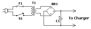
DC Power Supply Schematic
C1 6800uF 25V Electrolytic Capacitor
T1 3A 15V Transformer
BR1 5A 50V Bridge Rectifier 10A 50V Bridge Rectifier
S1 5A SPST Switch
F1 4A 250V Fuse
If you want to use the auto battery charger without having to provide an external power supply, use above circuit. The first time you use the circuit, you should check up on it every once and a while to make sure that it is working properly andthe battery is not being over charged.
Source: Car Battery Charger

Auto Battery Charger 12V


This auto battery charger uses no transformer, rectifier, or filter capacitors on the schematic. No reason why you cannot add these. This charger will quickly and easily charge most any lead acid battery. The charger delivers full current until the current drawn by the battery falls to 150 mA. At this time, a lower voltage is applied to finish off and keep from over charging. When the battery is fully charged, the circuit switches off and lights a LED, telling you that the cycle has finished.
Auto Battery Charger Schematic
A heatsink will be needed for this auto battery charger ( U1.)
Auto Battery Charger Parts List
Resistor
R1 500 Ohm 1/4 W
R2 3K 1/4 W
R3 1K 1/4 W
R4 15 Ohm 1/4 W
R5 230 Ohm 1/4 W
R6 15K 1/4 W
R7 0.2 Ohm 10 W
Capacitor
C1 0.1uF 25V Ceramic
C2 1uF 25V Electrolytic
C3 1000pF 25V Ceramic
Diode
D1 1N457
Transistor
Q1 2N2905 PNP
Regulator
U1 LM350
Op Amp
U2 LM301A
S1 Normally Open Push Button Switch
MISC Wire, Board, Heatsink For U1, Case, Binding Posts or Alligator Clips For Output
To use the circuit, hook it up to a power supply/plug it in. Then, connect the battery to be charged to the output terminals. All you have to do now is push S1 (the “Start” switch), and wait for the circuit to finish.
DC Power Supply Schematic
C1 6800uF 25V Electrolytic Capacitor
T1 3A 15V Transformer
BR1 5A 50V Bridge Rectifier 10A 50V Bridge Rectifier
S1 5A SPST Switch
F1 4A 250V Fuse
If you want to use the auto battery charger without having to provide an external power supply, use above circuit. The first time you use the circuit, you should check up on it every once and a while to make sure that it is working properly andthe battery is not being over charged.
Source: Car Battery Charger

Auto Battery Charger 12V Circuit schematic with description


This auto battery charger uses no transformer, rectifier, or filter capacitors on the schematic. No reason why you cannot add these. This charger will quickly and easily charge most any lead acid battery. The charger delivers full current until the current drawn by the battery falls to 150 mA. At this time, a lower voltage is applied to finish off and keep from over charging. When the battery is fully charged, the circuit switches off and lights a LED, telling you that the cycle has finished.
Auto Battery Charger Schematic
A heatsink will be needed for this auto battery charger ( U1.)
Auto Battery Charger Parts List
Resistor
R1 500 Ohm 1/4 W
R2 3K 1/4 W
R3 1K 1/4 W
R4 15 Ohm 1/4 W
R5 230 Ohm 1/4 W
R6 15K 1/4 W
R7 0.2 Ohm 10 W
Capacitor
C1 0.1uF 25V Ceramic
C2 1uF 25V Electrolytic
C3 1000pF 25V Ceramic
Diode
D1 1N457
Transistor
Q1 2N2905 PNP
Regulator
U1 LM350
Op Amp
U2 LM301A
S1 Normally Open Push Button Switch
MISC Wire, Board, Heatsink For U1, Case, Binding Posts or Alligator Clips For Output
To use the circuit, hook it up to a power supply/plug it in. Then, connect the battery to be charged to the output terminals. All you have to do now is push S1 (the “Start” switch), and wait for the circuit to finish.
DC Power Supply Schematic
C1 6800uF 25V Electrolytic Capacitor
T1 3A 15V Transformer
BR1 5A 50V Bridge Rectifier 10A 50V Bridge Rectifier
S1 5A SPST Switch
F1 4A 250V Fuse
If you want to use the auto battery charger without having to provide an external power supply, use above circuit. The first time you use the circuit, you should check up on it every once and a while to make sure that it is working properly andthe battery is not being over charged.
Source: Car Battery Charger

Car Battery Charger12V circuit and explanation


Cutting-Edge Technology - Battery Chargers
All car batteries have required a 12v battery charger. And this is also true of Marine, RV and Power Sports batteries. The high efficiency lead acid type batteries available today require more efficient charging techniques.

The most important factors in the life of your battery, the battery charger is the most valuable tool in saving the life of your battery, getting up and running and cutting your down time. Using the proper charger is crucial to your battery. Some manufacturers of gel cell, solar and AGM batteries will not honor warranties if the proper charger or 12 volt gel cell charger is not used.

High-Quality 12 Volt Battery Chargers
With the change of battery technology the computer chip has found its way into many of the higher quality battery chargers. With the use of microprocessor technology in battery chargers, you could say battery charging has become a science. Your battery will never overcharge and the trickle charge will always be maintained. It is fully automatic with float mode monitoring capabilities and uses high-frequency power conversion technology.

12V Car Battery Charger
Most car battery chargers are simple devices that continuously charge the battery with a few amperes for the duration it is ON. If the charger is not switched OFF in time, the battery will overcharge, its electrolyte lost due to evaporation, and its plate-element will likely be destroyed.

The 12 volt car battery charger circuit below will eliminate these problems by monitoring the batteries condition of charge through its retroactive control circuit by applying a high charge current until the battery is completely charged. When charging is complete, it turns on the red LED (LD2) and deactivates the charging circuit. This circuit is drawn to charge 12V batteries ONLY. Certain emphasis should be taken when wiring up this circuit. They are the connections of the transformer to the circuit board, and those supplying current to the battery being charged. These connections should be made with cables having a large cross-sectional area to prevent voltage-drop and heat build-up when current flows through them. See


Automatic 12V Lead Acid Battery Charger
This battery charger will charge any 12V lead acid battery including flooded, gel and AGM. It is fully automatic and will charge at a rate up to about 4A until the battery voltage reaches a preset point at which it will switch to a very low current float charge. If the battery voltage drops again the charger will begin charging until the voltage once again reaches the cut off point. In this way it can be left connected to a battery indefinitely to maintain full charge without causing damage. An LED indicates when the battery is fully charged.


You may be interested in reading: Power Adapters or Power Supplies

Rechargeable Charger and Batteries


There are four types of rechargeable batteries: nickel metal-hydride (NiMH), nickel cadmium (NiCad), rechargeable alkaline, and lithium ion.. They come in many different sizes and use different combinations of chemicals. And commonly used secondary cell chemistries are lead acid, nickel cadmium (NiCad), nickel metal hydride (NiMH), lithium ion (Li-ion), and lithium ion polymer (Li-ion polymer).


Types of Rechargeable Batteries
NiMH rechargeable batteries typically perform better than NiCads and are free of toxic heavy metals. Generally speaking, NiMH is the best all-around choice for most rechargeable battery applications. As an added bonus, most NiMH battery charger systems can accommodate NiCad batteries too (although the opposite is not true).

NiCads are being phased out in favor of NiMHs not only because they are losing the performance war, but also because of their inconvenience; the heavy metals used within the NiCad are toxic and require special disposal needs.

Rechargeable alkaline batteries have only two real advantages over NiMHs and NiCads: low cost and no need for special recycling. Otherwise, their long-term performance and recharge characteristics make these batteries a poor choice. Rechargeable alkaline batteries also require a special charger, which reminds me: don’t ever confuse rechargeable alkalines with the typical disposable alkaline batteries that are sold everywhere from 99-cent stores to the local grocery market – although some people do it, those batteries cannot be safely charged.

Lithium Ion batteries have great performance and can go unused for long periods without losing their charge. The big drawback is their price; not only are lithium ion batteries much more expensive than other types of rechargeable batteries, but they also require a special charger. Use them for rarely-used or high-drain devices like laptop computers, digital cameras, cell phones or portable television

Rechargeable Batteries Comparison Table
Here is a trade summary of the four basic options to help you decide which rechargeable battery is right for you. (lenpenzo dot com)


Click image to enlarge

Battery Charger
The energy used to charge rechargeable batteries mostly comes from AC current (mains electricity) using an adapter unit. Most battery chargers can take several hours to charge a battery. Most batteries can be charged in far less time than the most common simple battery chargers are capable of. Duracell and Rayovac now sell chargers that can charge AA- and AAA-size NiMH batteries in just 15 minutes; Energizer sells chargers that can additionally charge C/D-size and 9 V NiMH batteries. However, high rates of charging (eg. 15 minute charger, 1 hour chargers) will cause long term damage to NiMH and most other rechargeable batteries.


Best Battery Charger

Rechargeable batteries are susceptible to damage due to reverse charging if they are fully discharged. Fully integrated battery chargers that optimize the charging current are available.

Also, attempting to recharge non-rechargeable batteries has a small chance of causing a battery explosion.

Find on Amazon Rechargeable Batteries and Charger

using LP2951making Li-Ion Charger

The LP2951 regulator is manufactured by National Semiconductors. The choice of values is from an application note “Battery Charging”, written by Chester Simpson.

Diode D1 can be any diode from the 1N00x series, whichever is conveniently available. It functions as a blocking diode, to prevent a back flow of current from the battery into the LP2951 when the input voltage is disconnected.

Charging current is about 100+mA, which is the internally-limited maximum current of the LP2951. For those wondering, this is compatible with just about any single-cell li-ion battery since li-ion can generally accept a charging current of up to about 1c (i.e. charging current in mA equivalent to their capacity in mAh, so a 1100mAh li-ion cell can be charged at up to 1100mA and so on). A lower charging current just brings about a correspondingly longer charge time. IMHO 100mA is quite low, low enough that the circuit can be used for an overnight charger for many typical single-cell li-ion batteries.

The resistors are deliberately kept at large orders of magnitude (tens/hundred Kohm and Mohm range) to keep the off-state current as low as possible, at about 2?A. Resistor tolerances should be kept at 1% for output voltage accuracy. The 50k pot allows for an output voltage range between 4.08V to 4.26V – thus allowing calibration as well as a choice between a charging voltage of 4.1V or 4.2V depending on the cell to be charged. The capacitors are for stability, especially C2 which prevents the output from ringing/oscillating.
[...]
author: Izhar Fareed – izhargmx.us – extremecircuits.net

Lithium Ion – Lithium Poly Charger by LM317

Lithium Ion - Lithium Poly Charger by LM317

The above circuit will charge any 2-cell * Li-Ion battery pack. Maximum current is about 650 milliamps. The circuit is designed for batteries of 900mah or higher. Note this circuit is NOT for Li-Metal batts (i.e. Duralites). Power source can be a 12v Gell cell (Power panel), or can be powered by a car’s cigarette lighter. I use an old 12v DC wall transformer (800ma or more.) Radio shack sells a 12v/1amp wall DC adapter #273-1776 that will work. Supply does not need to be regulated. In fact my cheap supply outputs 17 volts with no load.

Read More Source:

http://www.shdesigns.org/lionchg.html

Thank you.

Auto Battery Charger 12V Car Charger This auto battery charger uses no transformer, rectifier, or filter capacitors on the schematic. No reason why

Auto Battery Charger 12V

Car Charger

This auto battery charger uses no transformer, rectifier, or filter capacitors on the schematic. No reason why you cannot add these. This charger will quickly and easily charge most any lead acid battery. The charger delivers full current until the current drawn by the battery falls to 150 mA. At this time, a lower voltage is applied to finish off and keep from over charging. When the battery is fully charged, the circuit switches off and lights a LED, telling you that the cycle has finished.

Auto Battery Charger Schematic

Auto Battery Charger Schematic

A heatsink will be needed for this auto battery charger ( U1.)

Auto Battery Charger Parts List
Resistor
R1 500 Ohm 1/4 W
R2 3K 1/4 W
R3 1K 1/4 W
R4 15 Ohm 1/4 W
R5 230 Ohm 1/4 W
R6 15K 1/4 W
R7 0.2 Ohm 10 W
Capacitor
C1 0.1uF 25V Ceramic
C2 1uF 25V Electrolytic
C3 1000pF 25V Ceramic
Diode
D1 1N457
Transistor
Q1 2N2905 PNP
Regulator
U1 LM350
Op Amp
U2 LM301A
S1 Normally Open Push Button Switch
MISC Wire, Board, Heatsink For U1, Case, Binding Posts or Alligator Clips For Output

To use the circuit, hook it up to a power supply/plug it in. Then, connect the battery to be charged to the output terminals. All you have to do now is push S1 (the “Start” switch), and wait for the circuit to finish.

DC Power Supply Schematic

C1 6800uF 25V Electrolytic Capacitor
T1 3A 15V Transformer
BR1 5A 50V Bridge Rectifier 10A 50V Bridge Rectifier
S1 5A SPST Switch
F1 4A 250V Fuse

If you want to use the auto battery charger without having to provide an external power supply, use above circuit. The first time you use the circuit, you should check up on it every once and a while to make sure that it is working properly and the battery is not being over charged.

See more: FM Antenna

Source: Car Battery Charger

Zinc-Carbon Battery charger circuit and explanation

They are cheap. The electrolyte used to leak but today they are usually much better protected. If they should leak then they will corrode all the copper in your equipment. the corrosion will travel down wires and eat its way through Printed Circuit Boards (PCBs). At high temperatures (25 degrees or more) Zinc-Carbon batteries will give up to 25% more capacity but the shelf-life will deteriorate very rapidly. Around freezing point their shelf-life can be extended by as much as 300% so one tip is to store them in the refrigerator.

Unfortunately they must be thrown away when they are exhausted. You can extend their life by up to 60% by using "Dirty-DC" to recharge them but this will also reduce the shelf-life.

Ry should be about 1.5 x greater than Rx. The resistors are determined by the charging current you want. With the circuit shown and size AA cells in a pack of ten cells, the battery voltage will be 15 volts. Discharge the battery to no less than 25%. To replace 350mA/H back into the battery over 10 hours we need to charge at 35mA.

Rx = (24 - 15 - 0.7) / (3 x 0.035) = 79 ohms

Ry = (24 - 15) / (2 x 0.035) = 128

You can also cook exhausted battery cells in the oven. About 80 degrees centigrade for five to ten minutes, no more or they may explode. This technique was demonstrated on UK TV in the series "Steptoe & Son" (h�r i Sverige i "Albert och Herbert"). I do not reccomend that you should try to sell the cells again as new batteries!

Source : http://web.telia.com/~u85920178/begin/batt-00.htm

For Lead/Acid 12V Battery Charger

12V Battery Charger for Lead/Acid

The battery charger circuit below is very simple to build requiring only a handful of cheap parts and an extra winding on your power tranny (or a separate tranny). Since the chargerdescribed is not active during sound reproduction, I have made no criteria on parts quality, so el-cheapo was the way to go.

There are many circuits available for charging batteries, but many are forNiCd or NiMH batteries. They will not work for lead/acide batteries, so don't use these!!! The best way to charge a battery is with a current limited voltage regulator. This sets a maximum current (say 1A) that will flow to charge the battery. If the current rises over this set current, the regulator will be forced to put out a lower voltage. Since voltage drops, so will the current; hence current limited. While thebattery is charging, the current should decrease slowly while voltage starts to increase. In the end the current will be next to zero and the voltage will be equal to the set voltage.


Use the following to design a charger:
  1. The charging current should be kept to around 0.1 times the capacity of the battery. So a 10Ah battery should be charged with 1A of current (10 x 0.1 = 1). The battery will not be forced (quick charged) this way and assures a longer lifetime.
  2. The charging voltage should be set to 2.3 - 2.4V per 2V cell. So a 12V battery (6 cells of 2V) is charged at 6 x 2.3 = 13.8V.
  3. The transformer winding for the charger supply is chosen at the charging voltage plus 3V regulator drop plus 1.4V rectifier drop (two diodes) plus 10% safety. So for a 2V battery, the winding (AC) is 2V + 3V + 0.7V + 0.7V = 6.4V + 10% = 7V.
  4. The charging current is limited by the small resistor in the common leg of the charger. The value for this resistor can be calculated with: R = 0.6V / max current. So if I want a maximum current of 0.5A, I will need 0.6V / 0.5A = 1.2 ohms. The 0.6V is the voltage required for the transistor to go fully into conduction. Between 0V and 0.6V the transistor will adjust the regulator to increase or decrease voltage depending on the current it is passing.
  5. The charging voltage can be set using the potentiometer. Just hook up a volt-meter to the charger (without the battery attached) and adjust the output voltage until it macthes the charging voltage. Use a 1K pot for 2V batteries, use 5K for 6V and 12V batteries.
  6. Use an extra fuse on the charger, about two times the maximum current you are charging with. Fusing is critical for safety reasons. A battery can deliver 100+ amperes during a short, so it can cause serious damage or even fires when something goes wrong with the charger. Put the fuse behind the regulator in the lead going to thebattery. This fuse is not to protect the supply from a short in the charger, but to protect everything else from the battery in case of a short anywhere. Don't forget to fuse the primary winding of thecharger as well...
  7. You're set up to charge...
The diode over the regulator in my schematic prevents damage to the regulator when the supply is turned off. In this situation the battery that is still attached offers a negative voltage over the regulator, as the voltage on the output is greater than the voltage on the input. The diode shorts the regulator in this situation and avoids any problems. It is just a safety. Source: Lead/acid battery charger

intelligent battery charger PIC16F628


I found this project on this forum
edaboard and I buil it,tested and it works but there is several things need to be calibrated correctly to run the charger properly.
On the forum you will found all you need.
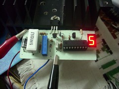
Here is some photos of my charger and schematic.


Car Battery Charger description and circuit diagram

This charger will quickly and easily charge most any lead acid battery. The charger delivers full current until the current drawn by the battery falls to 150 mA. At this time, a lower voltage is applied to finish off and keep from over charging. When the battery is fully charged, the circuit switches off and lights a LED, telling you that the cycle has finished.

Circuit diagram

Parts
R1 500 Ohm 1/4 W Resistor
R2 3K 1/4 W Resistor
R3 1K 1/4 W Resistor
R4 15 Ohm 1/4 W Resistor
R5 230 Ohm 1/4 W Resistor
R6 15K 1/4 W Resistor
R7 0.2 Ohm 10 W Resistor
C1 0.1uF 25V Ceramic Capacitor
C2 1uF 25V Electrolytic Capacitor
C31000pF 25V Ceramic Capacitor
D1 1N457 Diode
Q1 2N2905 PNP Transistor
U1 LM350 Regulator
U2 LM301A Op Amp
S1Normally Open Push Button Switch
MISC Wire, Board, Heatsink For U1, Case, Binding Posts or Alligator Clips For Output

Notes
1. The circuit was meant to be powered by a power supply, which is why there is no transformer, rectifier, or filter capacitors on the schematic. There is no reason why you cannot add these.
2. A heatsink will be needed for U1.
3. To use the circuit, hook it up to a power supply/plug it in. Then, connect the battery to be charged to the output terminals. All you have to do now is push S1 (the "Start" switch), and wait for the circuit to finish.
4. If you want to use the charger without having to provide an external power supply, use the following circuit.

C1 6800uF 25V Electrolytic Capcitor
T1 3A 15V Transformer
BR1 5A 50V Bridge Rectifier 10A 50V Bridge Rectifier
S1 5A SPST Switch
F1 4A 250V Fuse

5. The first time you use the circuit, you should check up on it every once and a while to make sure that it is working properly and the battery is not being over charged.


author:
e-mail:
sourc web site: http://www.aaroncake.net

Battery Charger circuit for car

This charger will quickly and easily charge most any lead acid battery. The charger delivers full current until the current drawn by the battery falls to 150 mA. At this time, a lower voltage is applied to finish off and keep from over charging. When the battery is fully charged, the circuit switches off and lights a LED, telling you that the cycle has finished.

Circuit diagram

Parts
R1 500 Ohm 1/4 W Resistor
R2 3K 1/4 W Resistor
R3 1K 1/4 W Resistor
R4 15 Ohm 1/4 W Resistor
R5 230 Ohm 1/4 W Resistor
R6 15K 1/4 W Resistor
R7 0.2 Ohm 10 W Resistor
C1 0.1uF 25V Ceramic Capacitor
C2 1uF 25V Electrolytic Capacitor
C31000pF 25V Ceramic Capacitor
D1 1N457 Diode
Q1 2N2905 PNP Transistor
U1 LM350 Regulator
U2 LM301A Op Amp
S1Normally Open Push Button Switch
MISC Wire, Board, Heatsink For U1, Case, Binding Posts or Alligator Clips For Output

Notes
1. The circuit was meant to be powered by a power supply, which is why there is no transformer, rectifier, or filter capacitors on the schematic. There is no reason why you cannot add these.
2. A heatsink will be needed for U1.
3. To use the circuit, hook it up to a power supply/plug it in. Then, connect the battery to be charged to the output terminals. All you have to do now is push S1 (the "Start" switch), and wait for the circuit to finish.
4. If you want to use the charger without having to provide an external power supply, use the following circuit.

C1 6800uF 25V Electrolytic Capcitor
T1 3A 15V Transformer
BR1 5A 50V Bridge Rectifier 10A 50V Bridge Rectifier
S1 5A SPST Switch
F1 4A 250V Fuse

5. The first time you use the circuit, you should check up on it every once and a while to make sure that it is working properly and the battery is not being over charged.


author:
e-mail:
web site: http://www.aaroncake.net