Showing posts with label Automotive Circuits. Show all posts

Mains Frequency Monitor circuit and explanation

Here is a simple frequency counter designed to monitor the 240VAC mains supply. It as a frequency range of 0-999Hz, so it could also be used with 400Hz equipment. Standard TTL/CMOS logic is employed for the counters and display drivers, while an ELM446 (IC1) generates accurate 1Hz pulses for gating. This device utilizes a 3.579545MHz crystal for its timebase, as commonly found in TV and video circuits and even on old PC motherboards.

Circuit diagram:
Mains frequency monitor circuit schematic
Mains Frequency Monitor Circuit Diagram
Copyright: Silicon Chip Electronics Magazine

LM555 Timer F to V Converter Circuit and explanation

Description.

Here is a very simple circuit diagram of a frequency to voltage (F to V) converter. Such a circuit finds numerous applications in projects like digital frequency meters, tachometers etc. The circuit is mainly based on a LM555 timer IC. The IC is wired in mono shot mode to convert the input frequency into a fixed pulse width, variable frequency PWM signal. Resistors R4 and capacitor C2 provides the necessary timing for the circuit. The transistor T1 forms a discharge path parallel to C2 which is necessary for re triggering the IC. Capacitor C1 acts as an input DC decoupler.

Circuit diagram.


LM555 Timer F to V Converter Circuit and explanation


Notes.

  • The circuit can be assembled on a Vero board.
  • Use 12V DC for powering the circuit.
  • LM555 must be mounted on a holder.
  • The output of the circuit is not a pure DC but a PWM waveform. Additional circuitry is required to convert this PWM waveform to pure DC.

Read more: http://www.circuitstoday.com/category/automotive-circuits/page/3#ixzz1HPGekdw8

LM1875 20W audio amplifier circuit and explanation

Description.
This is just another 20W audio amplifier circuit , but this time based on the LM1875 audio amplifier IC from National Semiconductors. With a 25V dual power supply LM1875 can deliver 20W of audio power into a 4 ohm speaker. The LM1875 requires very less external components and has very low distortion. The IC is also packed with a lot good features like fast slew rate, wide supply voltage range, high output current, high output voltage swing, thermal protection etc. The IC is available in TO-220 plastic power package and is well suitable for a variety of applications like audio systems, servo amplifiers, home theatre systems etc.
Circuit diagram.

Notes.
 LM1875 20W audio amplifier circuit and explanation
  • Assemble the circuit on a good quality PCB.
  • Use +/-25V DC dual supply for powering the circuit.
  • K1 can be 4 ohm, 20W speaker.
  • A proper heat sink is necessary for the IC.
  • F1 and F2 are 2A fuses.


Read more: http://www.circuitstoday.com/category/automotive-circuits/page/2#ixzz1HPDvsBfT

TDA2040 Car stereo amplifier circuit and explanation

TDA2040 Car stereo amplifier circuit and explanation

Car Audio Amplifier Circuit:

Given below is a car stereo amplifier circuit using audio amplifier IC – TDA2040

Description of the circuit:

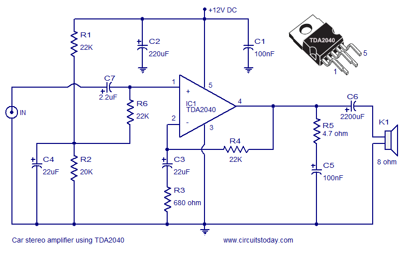
A car stereo amplifier circuit using TDA2040 is shown here. TDA2040 is a monolithic integrated audio amplifier that operates in Class AB mode. The IC has built in circuitry for short circuit protection and thermal shut down and more over it can be operated from a single supply too. The amplifier can deliver 12 watts into to a 8 ohm speaker.

In the circuit the IC is wired in order to operate from the cars 12V line. Capacitor C7 is the input DC decoupling capacitor and R4 provides feedback. Network consisting of resistor R5 and capacitor C5 provides high frequency stability and prevents any chance of oscillation. Capacitor C6 couples the ICs output to the speaker. C2 and C1 are power supply filters.

Circuit diagram of car stereo circuit using TDA2040


Car amplifier circuit diagram

Notes.

  • Quality of the PCB is a very crucial factor in the amplifiers performance.
  • The amplifier can be operated from cars 12V line.
  • Heat sink is necessary for TDA2040.
  • All electrolytic capacitors must be rated 15V.
  • Only one channel is shown here. For stereo application you must make one more identical copy.

Read more: http://www.circuitstoday.com/category/automotive-circuits#ixzz1HNAmdy8H
Under Creative Commons License: Attribution