Showing posts with label Converter. Show all posts

DC- DC Converter 12V to 24V Circuit schematic with decription

This simple circuit is a DC-DC converter that converting up 12V source to a 24V. It can be used to run radios, small lights, relays, horns and other 24V accessories from a 12V vehicle with a maximum draw of about 800mA.
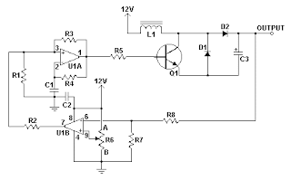

This DC-DC Converter can be used to charge one 12V battery from another, or step up the voltage just enough to provide necessary overhead for a 12V linear regulator. Using one op-amp as a squarewave oscillator to ring an inductor and another op-amp in a feedback loop, it won't drift around under varying loads, providing a stable 24V source for many applications. With a wide adjustment in output this circuit has many uses.

Parts List
R1-R4,R7-R8 100K 1/4W Resistor
R5 470 Ohm 1/2W Resistor
R6 10K Linear Pot
C1 0.01uF Mylar Capacitor
C2 0.1uF Ceramic Disc Capacitor
C3 470uF 63V Electrolytic Capacitor
D1 1N4004 Rectifier Diode
D2 BY229-400 Fast Recovery Diode See Notes
Q1 BC337 NPN Power Transistor
U1 LM358 Dual Op Amp IC
L1 See Notes
MISC Board, Wire, Socket For U1, Case, Knob For R6, Heatsink for Q1

DC- DC Converter Notes
1. R6 sets the output voltage. This can be calculated by Vout = 12 x (R8/(R8+R7)) x (R6B/R6A).
2. L1 is made by winding 60 turns of 0.63MM magnet wire on a toroidial core measuring 15MM (OD) by 8MM (ID) by 6MM (H).
3. D2 can be any fast recovery diode rated at greater then 100V at 5A. It is very important that the diode be fast recovery and not a standard rectifier.
4. Q1 will need a heatsink.

Source : 12V To 24V DC-DC Converter Circuit

LT3433 based Step Up/Step Down DC to DC Converter Circuit Diagram circuit with explanation

LT3433 based Step Up/Step Down DC to DC Converter Circuit Diagram circuit with explanation
The illustration provides below schemes 8V-60V to 12V Converter Circuit Diagram. It uses LT3433, an automatic step up and step down switching regulator IC with 4V to 60V input voltage which can be useful in automotive electronics using various wide input voltage range.

According to the LT3433 datasheet, this Automatic Step-Up and Step-Down Conversion device is a 200kHz fixed frequency current mode switching regulator using a single inductor which can be applied in applications such as wall adapter powered systems and battery power voltage buffering.

Read completely about Step Up/Step Down DC to DC Converter Circuit Diagram using LT3433 here in pdf archive (source: linear.com)

RGB To Color Difference Converter circuit and explanation

The circuit diagram shows two LT1398’s from Linear Technology used to create buffered color-difference signals from RGB (red-green-blue) inputs. In this application, the R input arrives via 75Ω coax. It is routed to the non-inverting input of amplifier IC1a and to 1.07-kΩ resistor, R8. There is also an 80.6-Ω termination resistor R11, which yields a 75-Ω input impedance at the R input when considered in parallel with R8. R8 connects to the inverting input of a second LT1398 amplifier (IC1b), which also sums the weighted G and B inputs to create a –0.5Y output.

RGB To Color Difference Converter circuit diagramYet another LT1398 amplifier, IC2a, then takes the –0.5Y output and amplifies it by a gain of –2, resulting in the +Y output. Amplifier IC1a is configured for a non-inverting gain of 2 with the bottom of the gain resistor R2 tied to the Y output. The output IC1a thus results in the color-difference output R–Y. The B input is similar to the R input. Here, R13 when considered in parallel with R10 yields a 75-Ω input impedance. R10 also connects to the inverting input of amplifier IC1b, adding the B contribution to the Y signal as discussed above.

PSU RGB To Color Difference ConverterAmplifier IC2b is configured to supply a non-inverting gain of 2 with the bottom of the gain resistor R4 tied to the Y output. The output of IC2b thus results in the color-difference output B–Y. The G input also arrives via 75-Ω coax and adds its contribution to the Y signal via resistor R9, which is tied to the inverting input of amplifier IC1b. Here, R12 and R9 provide the 75Ω termination impedance. Using superposition, it is straightforward to determine the output of IC1b. Although inverted, it sums the R, G and B signals to the standard proportions of 0.3R, 0.59G and 0.11B that are used to create the Y signal. Amplifier IC2a then inverts and amplifies the signal by 2, resulting in the Y output. The converter draws a current of about 30mA from a symmetrical 5-volt supply.

IC 555 12VDC to 220VAC Inverter Circuit and explanation

This is a simple 12VDC to 220AC inverter circuit that can be used produces an AC output at line frequency and 220AC or different voltage by selecting transformer T1. The 555 IC is configured as a low-frequency oscillator, tunable over the frequency range of 50 to 60 Hz by Frequency potentiometer R4.

12VDC to 220VAC Inverter Circuit 12VDC to 220VAC Inverter Circuit

The 555 feeds its output (amplified by Q1 and Q2) to the input of transformer T1, a reverse-connected filament transformer with the necessary step-up turns ratio. Capacitor C4 and coil L1 filter the input to T1, assuring that it is effectively a sine wave. Adjust the value of T1 to your voltage. The output ( in watts) is up to you by selecting different components.

Input voltage is anywhere from +5V to +15Volt DC, adjust the 2700uF cap's working voltage accordingly. Replacement types for Q1 are: TIP41B, TIP41C, NTE196, ECG196, etc. Replacement types for Q2 are: TIP42B, TIP42C, NTE197, ECG197, etc.

110V converter to convert 12V DC voltage from the battery into 110V or 220V AC

12V to 110V Converter

The meaning here is the 110V converter to convert 12V DC voltage from the battery into 110V or 220V AC. Let us call this the DC to AC inverter. Why is that, because the term converter is usually devoted to a type of voltage conversion, for example, from AC to AC through a transformer, or DC to DC using an electronic circuit for it.
240V/220V to 120V/110V converter is better known as the step-up or step-down voltage converter. To convert AC voltage (AC) is very easy, just use a transformer that has the specifications mentioned above. With proper wiring, you have to use the tools immediately.
We return to our original topic, which is the 110V converter. For that we need a 12V car battery as a source, and through a converter chart below, we expect the output 110V AC voltage, which can be used to run any electronic equipment that requires AC power voltage as the source.
In this article, 110V converter details are not discussed because it was already explained in previous articles. That is just the key points that the 12V inverter or 110V converter can be used in power load to 120 Watts. The selected transformer capacity of 10A (P = VxI, 120×10 = 120W). However, this also needs to be adjusted towith the power MOSFETs used in this converter circuit if you use a transformer with a larger ampere.
Necessary components in this converter circuit, in addition to passive components, such as the diodes, resistor, capacitors and other consist of CMOS Hex Inverter IC CD4069UB used to generate the square wave. For a given voltage to the IC is an IC regulator 7805 will be used.
110V Converter Circuit Schematic
Square wave will be amplified by the transistor 2SC1815 and forwarded to the final amplifier in the form of a pair of transistor MOSFET 2SJ471 and 2SK2956. By using a transformer that passed through the 12V voltage is fed to the Drain (D) MOSFETs to convert DC to AC voltage on the transformer primary coil. The current will flow alternatively in through the primary windings of the transformer since the MOSFET is configured as bridge.
If you want to modify the 220V/110v converter circuit, please learn more about the principles of  electrical voltage conversion. Because what you find in this article are the basic stage

DC-DC 12V to 120V Converter Circuit

Here is a simple DC DC converter schematic using a saturation-limited to push-pull converter. DC converter can be used to power the VCR from a car battery and glow plug light aircraft models from a 12V battery starter

.

As a final amplifier of the DC DC converter is a pair of transistor MJE2955 and 2SC945 as oscillator to apply sufficient bias to the final amplifier transistors.

The 2SC945 is a bias switch for startup. When applying 12V power, this transistor applies enough bias to the power transistors to get the oscillation started. Soon later, the 100uF capacitor charges up, the transistor goes off, and the power transistors self-bias into cut-off, such that cross-conduction is eliminated. After removing power, the 6k8 resistor discharges the bias timing capacitor, as otherwise the circuit would be unable to restart!

The secondary rectifiers are ultrafast diodes. These are NOT 1N4007! And the 220nF capacitors for the secondary filter are no typos; the diodes deliver almost pure DC, since the oscillation waveform is square, so only some noise filtering is needed. No electrolytics are necessary here.


DC DC Converter

Note the filters at both input and output, using ferrite cores. These are necessary to avoid polluting your environment with RF noise! Using these filters, and joining the input and output negative leads, this converter is very quiet and does not cause any problem in my combined HF, VHF and UHF station.

All ferrite cores (for the transformer and for the noise filters) are manufactured by Amidon Associates, and can be ordered directly from them in small quantities. Look for Amidon on the web. The 77-material core used for the transformer is less than ideal. A square-loop ferrite would work more efficiently! This one gets really warm, operating in saturation mode at 25 kHz. But it has worked well enough for two years now. The filter cores, on the other hand, are well chosen, so try to use the exact ones.

For all windings, the schematic states the number of turns. “7t” means 7 turns. As the transformer is quite small for the involved power, use as thick a wire as you can fit, leaving about half of the space for the 2×7 turns primary winding, and the other half for the secondary, while the feedback winding can be made from very thin wire.

The transistors do not need any heat sinks. They are large enough without, and they need to dissipate little heat!

LM2585 12V to 28V DC-DC Converter

12V to 28V DC-DC Converter with LM2585 Skema

12V to 28V DC-DC Converter with LM2585 PCB

This boost regulator is for those times when you have a 28v relay, but want to use it with a 12v source. The circuit is built around the National Semiconductor LM2585, and uses the energy stored in an inductor to boost the 12v to 28. Output voltage can be varied by adjusting the ratio of resistor values on the feedback pin.

The circuit does it’s switching around 100 Khz, but generates no noise if SMT components are used. Output is good for about half an amp continuous, enough to power two or three large microwave relays. The board measures 1.5″x2″.

It is important to note at least these three cautions before powering up the board:

  1. A short-circuit on the output will kill U1 and D1. Always use a 1 ohm 5w resistor, or a 2.5A fast fuse on the 12v input lead.
  2. Do not omit the LED (D2); It provides a visual indicator of a properly operating boost condition, but more importantly, it also provides a minimum load for the output, preventing an output “spike” which will otherwise appear when the load is disconnected abruptly.
  3. Keep the ratio of r2 and r3 to 22 or less to keep the output voltage within the ratings of C4 (C4 on my board is rated at 35wvdc). This ratio plus 1, multiplied times 1.25v, determines the output voltage.
If you are using a PC board I supplied, please refer to this component identification picture, and the schematic below. A close-up picture, to assist with component placement, can be seen here.

LM2585 using 12V to 28V DC-DC Converter

12V to 28V DC-DC Converter with LM2585 Skema


12V to 28V DC-DC Converter with LM2585 PCB

This boost regulator is for those times when you have a 28v relay, but want to use it with a 12v source. The circuit is built around the National Semiconductor LM2585, and uses the energy stored in an inductor to boost the 12v to 28. Output voltage can be varied by adjusting the ratio of resistor values on the feedback pin.

The circuit does it's switching around 100 Khz, but generates no noise if SMT components are used. Output is good for about half an amp continuous, enough to power two or three large microwave relays. The board measures 1.5"x2".

It is important to note at least these three cautions before powering up the board:

  1. A short-circuit on the output will kill U1 and D1. Always use a 1 ohm 5w resistor, or a 2.5A fast fuse on the 12v input lead.
  2. Do not omit the LED (D2); It provides a visual indicator of a properly operating boost condition, but more importantly, it also provides a minimum load for the output, preventing an output "spike" which will otherwise appear when the load is disconnected abruptly.
  3. Keep the ratio of r2 and r3 to 22 or less to keep the output voltage within the ratings of C4 (C4 on my board is rated at 35wvdc). This ratio plus 1, multiplied times 1.25v, determines the output voltage.
If you are using a PC board I supplied, please refer to this component identification picture, and the schematic below. A close-up picture, to assist with component placement, can be seen here.

DC DC Converter 12V to 120V

Here is a simple DC DC converter schematic using a saturation-limited to push-pull converter. DC converter can be used to power the VCR from a car battery and glow plug light aircraft models from a 12V battery starter.

As a final amplifier of the DC DC converter is a pair of transistor MJE2955 and 2SC945 as oscillator to apply sufficient bias to the final amplifier transistors.

The 2SC945 is a bias switch for startup. When applying 12V power, this transistor applies enough bias to the power transistors to get the oscillation started. Soon later, the 100uF capacitor charges up, the transistor goes off, and the power transistors self-bias into cut-off, such that cross-conduction is eliminated. After removing power, the 6k8 resistor discharges the bias timing capacitor, as otherwise the circuit would be unable to restart!

The secondary rectifiers are ultrafast diodes. These are NOT 1N4007! And the 220nF capacitors for the secondary filter are no typos; the diodes deliver almost pure DC, since the oscillation waveform is square, so only some noise filtering is needed. No electrolytics are necessary here.

12V DC to 120V DC Converter Circuit

DC DC Converter

Note the filters at both input and output, using ferrite cores. These are necessary to avoid polluting your environment with RF noise! Using these filters, and joining the input and output negative leads, this converter is very quiet and does not cause any problem in my combined HF, VHF and UHF station.

All ferrite cores (for the transformer and for the noise filters) are manufactured by Amidon Associates, and can be ordered directly from them in small quantities. Look for Amidon on the web. The 77-material core used for the transformer is less than ideal. A square-loop ferrite would work more efficiently! This one gets really warm, operating in saturation mode at 25 kHz. But it has worked well enough for two years now. The filter cores, on the other hand, are well chosen, so try to use the exact ones.

For all windings, the schematic states the number of turns. “7t” means 7 turns. As the transformer is quite small for the involved power, use as thick a wire as you can fit, leaving about half of the space for the 2×7 turns primary winding, and the other half for the secondary, while the feedback winding can be made from very thin wire.

The transistors do not need any heat sinks. They are large enough without, and they need to dissipate little heat!

S: circuitelectronic.net/dc-dc-converter/

Frequency VoltageLM331 Converter Circuit and explanation

LM331 Frequency Voltage Converter Circuit


LM331 is basically a attention voltage to abundance advocate from National Semiconductors. The IC has a duke abounding of applications like analog to agenda conversion, continued appellation integration, voltage to abundance conversion, abundance to voltage conversion. Wide activating ambit and accomplished breadth makes the IC able-bodied acceptable for the applications mentioned above.

Here the LM331 is active as a abundance to voltage advocate which converts the ascribe abundance into a proportional voltage which is acutely beeline to the ascribe frequency. The abundance to voltage about-face is accomplished by appropriate the ascribe abundance application capacitor C3 and resistor R7 and agriculture the resultant beating alternation to the pin6 (threshold) of the IC. The abrogating activity bend of the resultant beating alternation at pin6 makes the congenital comparator ambit to activate the timer circuit. At any instant, the accepted abounding out of the accepted achievement pin (pin 6) will be proportional to the ascribe abundance and amount of the timing apparatus (R1 and C1). As a aftereffect a voltage (Vout) proportional to the ascribe abundance (Fin) will be accessible beyond the amount resistor R4.

Notes.

* The ambit can be accumulated on a vero board.

* I acclimated 15V DC as the accumulation voltage (+Vs) while testing the circuit.

* The LM331 can be operated from annihilation amid 5 to 30V DC.

* The amount of R3 depends on the accumulation voltage and the blueprint is R3= (Vs – 2V)/ (2mA).

* According to the equation, for Vs = 15V, R3=68K.

* The achievement voltage depends on the equation, Vout = ((R4)/(R5+R6))*R1C1*2.09V*Fin.

* POT R6 can be acclimated for calibrating the circuit.

USB Audio D/A Converter This electronic circuit is an high quality preamplifier with built-in DAC from SPDIF or USB for my power amplifier Leachamp.

This electronic circuit is an high quality preamplifier with built-in DAC from SPDIF or USB for my power amplifier Leachamp. I had available circuit PCM2902. I tried to design DAC from USB with this circuit on one-sided PCB and I was succesful.


Schematics is from datasheet of PCM2902. Circuit includes DAC and ADC, SPDIF output and input and HID part with 3 buttons for MUTE, VOL+ and VOL-. I used only DAC part. Other parts are not used. For high quality playback is needed to use external low-drop voltage stabiliser for DAC part. I used LP2951CM which was available at local store. Output voltage is set to about 3.7V with two resistors. Circuit board is designed regarding to good ground placement and separating of analog and digital ground. These ground are connected in one point at USB connector.


Source: http://www.pavouk.org/hw/usbdac/en_index.html

12V to 120V DC DC Converter Circuit Here is a simple DC DC converter schematic using a saturation-limited to push-pull converter. DC converter can be

12V to 120V DC DC Converter Circuit

Here is a simple DC DC converter schematic using a saturation-limited to push-pull converter. DC converter can be used to power the VCR from a car battery and glow plug light aircraft models from a 12V battery starter.

As a final amplifier of the DC DC converter is a pair of transistor MJE2955 and 2SC945 as oscillator to apply sufficient bias to the final amplifier transistors.

The 2SC945 is a bias switch for startup. When applying 12V power, this transistor applies enough bias to the power transistors to get the oscillation started. Soon later, the 100uF capacitor charges up, the transistor goes off, and the power transistors self-bias into cut-off, such that cross-conduction is eliminated. After removing power, the 6k8 resistor discharges the bias timing capacitor, as otherwise the circuit would be unable to restart!

The secondary rectifiers are ultrafast diodes. These are NOT 1N4007! And the 220nF capacitors for the secondary filter are no typos; the diodes deliver almost pure DC, since the oscillation waveform is square, so only some noise filtering is needed. No electrolytics are necessary here.

12V DC to 120V DC Converter Circuit

DC DC Converter

Note the filters at both input and output, using ferrite cores. These are necessary to avoid polluting your environment with RF noise! Using these filters, and joining the input and output negative leads, this converter is very quiet and does not cause any problem in my combined HF, VHF and UHF station.

All ferrite cores (for the transformer and for the noise filters) are manufactured by Amidon Associates, and can be ordered directly from them in small quantities. Look for Amidon on the web. The 77-material core used for the transformer is less than ideal. A square-loop ferrite would work more efficiently! This one gets really warm, operating in saturation mode at 25 kHz. But it has worked well enough for two years now. The filter cores, on the other hand, are well chosen, so try to use the exact ones.

For all windings, the schematic states the number of turns. “7t” means 7 turns. As the transformer is quite small for the involved power, use as thick a wire as you can fit, leaving about half of the space for the 2×7 turns primary winding, and the other half for the secondary, while the feedback winding can be made from very thin wire.

The transistors do not need any heat sinks. They are large enough without, and they need to dissipate little heat!

S/PDIF to Analogue Converter

This is quite possibly the simplest S/PDIF receiver and DAC available. It uses the absolute minimum of parts, and also minimises the connections and control functionality usually provided. It is still a serious project, and is not recommended for beginners. As shown, the connection is COAX (but will almost certainly handle TTL just as well). If you want a dedicated TTL to COAX converter, there is an adapter shown at the end of this article. The spare gates in the 74HC04 package may be used for the adapter if desired.
http://sound.westhost.com/project85.htm

Step Down DC-to-DC Converter ADP1821

This is a ADP1821 Step Down DC-to-DC Converter circuit. This circuit uses ADP1821 that is synchronous pulse-width-modulated (PWM), step-down controller, inexpensive and versatile. It can drive all N-channel power stage to regulate an output voltage as low as 0.6 V. The output voltages that can be provided by this circuit is from 0.6 V to …[Read More]